GSi 40-SERIES Скачать руководство пользователя страница 117

Chapter 8: Roof Assembly

Attaching the A-Frame to the Eave Bracket

The bottom end of the A-frame rafters must be installed to the eave brackets.

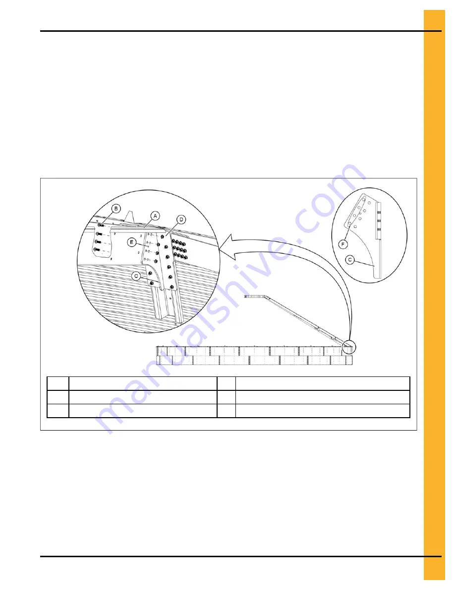
1. Lower the A-frame rafter assembly (A) along the side of the eave bracket (C), and align with the

holes nearest to the center collar.

NOTE:

Use the alignment hole (E) in the rafter to help align the holes with a punch tool.

2. Install flange bolts (B) and flange nuts (D), securing one side on the A-frame assembly to the eave

bracket (C).

3. Repeat this procedure for the other side of the A-frame.

4. Tighten to the recommended torque specifications. See

Bolt Torque Specifications, page 28

.

Figure 8-20

Attaching the rafter to the eave bracket

A

A-frame rafter assembly

D

1/2 in. flange nut (S-10253)

B

1/2 x 1-3/4 in. flange bolt (S-10252)

E

Hole for alignment tool

C

Eave bracket (CTR-0429)

After You Finish

Continue to the next A-frame installation until all of the A-frame rafter assemblies are installed. See

About

Temperature Cable Brackets and A-Frame Assemblies, page 96

.

PNEG-4472

72 Ft Diameter Z-Tek Bins

117

Содержание 40-SERIES

Страница 1: ...72 Ft Diameter Bin All Rings Models 40 SERIES 4 00 IN CORRUGATION BINS 30000 LB PEAK LOAD ROOF WITH CTS STIFFENERS Construction Manual PNEG 4472 Version 3 0 Date 06 07 18 PNEG 4472 ...

Страница 2: ...rations photos and specifications in this manual are based on the latest information available at the time of publication The right is reserved to make changes at any time without notice 2 PNEG 4472 72 Ft Diameter Z Tek Bins ...

Страница 3: ...S 10260 31 Bolt S 7483 31 Bolt S 7485 31 Bolt S 7487 32 Bolt S 7488 32 Bolt S 10252 33 Bolt S 10261 33 Chapter 4 Assembling Sidewall Sheets 35 Guidelines for Constructing Sidewall Sheets 35 Color Codes for Sidewall Gauge Identification 35 Gauge Sheet 36 Orientation Detail for Top Sidewall Sheets 37 Caulking and Bolting Detail for Standard Sidewall Sheets 38 Caulking Detail for Laminated Sheets 40 ...

Страница 4: ...n Laminated Stiffeners with Insert 69 12 Bolt Pattern Laminated Stiffener to Laminated Base Stiffener with Inserts to a Base Boot 70 12 Bolt Pattern Laminated Stiffener to Laminated Base Stiffener with an Inserts to a Base Boot 71 Chapter 7 Door Assembly 73 Door Assembly for Bins with All Rings Heights 74 Chapter 8 Roof Assembly 89 Attaching the Inside Stiffener to the Top Outside Stiffener 90 Att...

Страница 5: ...e Roof Exhauster 147 Installing Roof Exhauster Assembly 148 Installing the Manway Cover 151 Ladder Section Assembly 153 Inside Ladder Placement 154 Installing Inside Ladder Bottom Bracket 157 Guidelines for Installing a Sidedraw System 158 Locating the Chutes 160 Locating Discharge Opening 161 Sidewall Overlap 162 Caulking 163 Wind Ring Requirements 164 Installing Wind Rings 165 Assembling Weather...

Страница 6: ...NOTES 6 PNEG 4472 72 Ft Diameter Z Tek Bins ...

Страница 7: ...1 Safety Precautions Topics Covered in this Chapter Safety Guidelines for Bins Cautionary Symbol Definitions Safety Cautions Safety Decals Safety Sign off Sheet PNEG 4472 72 Ft Diameter Z Tek Bins 7 ...

Страница 8: ... having jurisdiction must be consulted before installations are made When necessary you must consider the installation location relative to electrical fuel and water utilities Personnel operating or working around equipment must read this manual This manual must be delivered with equipment to its owner Failure to read this manual and its safety instructions is a misuse of the equipment This produc...

Страница 9: ...symbol indicates an imminently hazardous situation which if not avoided will result in serious injury or death This symbol indicates a potentially hazardous situation which if not avoided can result in serious injury or death This symbol indicates a potentially hazardous situation which if not avoided can result in minor or moderate injury This symbol is used to address practices not related to pe...

Страница 10: ...structions Carefully read all safety messages in this manual and safety signs on your machine Keep signs in good condition Replace missing or damaged safety signs Be sure new equipment components and repair parts include the current safety signs Replacement safety signs are available from the manufacturer Learn how to operate the machine and how to use controls properly Do not let anyone operate w...

Страница 11: ...ition Replace worn or broken parts immediately ST 0003 1 Do Not Enter Bin Rotating flighting will kill or dismember Flowing material will trap and suffocate Crusted material will collapse and suffocate If you must enter the bin 1 Shut off and lock out all power sources 2 Use a safety harness and safety line 3 Station another person outside the bin 4 Avoid the center of the bin 5 Wear proper breath...

Страница 12: ...s or other air moving systems The manu facturer does not warrant this type of roof damage Adequate ventilation or makeup air devices must be pro vided for all powered air handling systems The manufacturer does not recommend the use of down ward flow systems suction Severe roof damage can result from any blockage of air passages Operating fans during high humidity or cold weather condi tions can ca...

Страница 13: ...nstallation Not following these safety precautions creates the risk of falling equipment which can crush personnel and cause serious injury or death ST 0047 1 Do Not Overfill the Bin Do not overfill bin Stored grain must be no higher than the roof eaves at the outer edge Filling the bin above this point creates excessive internal pressure and can cause swelling and eventual roof failure The over f...

Страница 14: ...The safest method of storing sidewall bundles is by laying them horizontally with the arch of the sheet upward like a dome Sidewall sheets stored on edge must be secured so that they cannot fall over and cause injury Use care when handling and moving sidewall bundles ST 0058 1 14 PNEG 4472 72 Ft Diameter Z Tek Bins ...

Страница 15: ...lved in the installation operation service and maintenance of the equipment To replace a damaged of missing decal contact us to receive a free replacement GSI Decals 1004 E Illinois Street Assumption IL 62510 Phone 1 217 226 4421 Location Decal No Decal Description Located next to aeration system DC 995 Caution Vacuum Pressure PNEG 4472 72 Ft Diameter Z Tek Bins 15 ...

Страница 16: ...1 Safety Precautions Location Decal No Decal Description On bin door covers DC GBC 1A Danger Keep Clear of Augers On bin door covers DC GBC 2A Warning Unload Instructions 16 PNEG 4472 72 Ft Diameter Z Tek Bins ...

Страница 17: ... off sheet that can be used to verify that all personnel have read and understood the safety instructions This sign off sheet is provided for your convenience and personal record keeping Date Employee Name Supervisor Name ST 0007 PNEG 4472 72 Ft Diameter Z Tek Bins 17 ...

Страница 18: ...NOTES 18 PNEG 4472 72 Ft Diameter Z Tek Bins ...

Страница 19: ...e sidewall and stiffeners You will also need to consult other instructions in building the bin These include but may not be limited to A stiffener and sidewall gauge layout chart If such a chart is not included with this manual contact GSI Roof instructions must be followed Roof instructions are included in this manual Ladders roof stairs roof handrails and other products are covered by separate i...

Страница 20: ...r bolt A is the minimum allowed 1 in diameter anchor bolt A is the mini mum with side draw flume system Exposed anchor bolt thread height B is 5 in Overall anchor bolt length C for 3 4 in and 1 in diameter anchor bolts is 18 in 45 72 cm Figure 2 1 Anchor bolt example 3 4 in diameter anchor bolt shown A Anchor bolt C Anchor bolt length B Anchor bolt thread height 20 PNEG 4472 72 Ft Diameter Z Tek B...

Страница 21: ...efer to the proper chart to find the anchor chord dimensions that correspond to the bin that is being built Start with one anchor bolt and work from it to the left to locate one quarter of the anchor bolts then to the right to locate another quarter of the bolts Working off of the last anchor bolts in each quarter locate the remaining anchor bolts in the last two quarters PNEG 4472 72 Ft Diameter ...

Страница 22: ... 36 2 1 2 10 973 48 Chord A Length ft and in m 1 4 8 7 8 1 219 2 9 5 7 16 2 743 3 14 1 9 16 4 267 4 18 8 15 16 5 486 5 23 3 3 8 7 010 6 27 8 9 16 8 230 Chord A Length ft and in m 7 32 0 3 8 9 754 8 36 2 9 19 10 973 9 40 2 13 16 12 192 10 44 1 1 16 13 411 11 47 9 14 326 12 51 2 1 2 15 545 22 PNEG 4472 72 Ft Diameter Z Tek Bins ...

Страница 23: ...dles on arrival for any moisture If moisture is present it must not be allowed to remain between the sheets Separate the sheets or panels immediately and wipe them down Spray with a light oil or diesel fuel If possible sidewall bundles roof sheets and other closely packed galvanized materials should be stored in a dry climate controlled building If outdoor storage is unavoidable the materials shou...

Страница 24: ...the bin during construction Lifting jacks must be properly sized and designed to carry all loads and job site conditions associated with the construction of the bin The number of lifting jacks required is best determined by personal experience and expertise Fac tors such as bin size jack design construction conditions support surface etc are all to be consid ered when deciding how many to use If i...

Страница 25: ... site 12 At the completion of the tank set stiffeners over the anchor bolts and measure the tank to ensure it is in a round condition Consult with GSI for questions on tolerances Guidelines for Placement of the Decal Sidewall Sheet Use the following as a general guideline the proper decal sheet placement NOTE Refer to the stiffener to sidewall attachment detail and specific gauge sheet for the bin...

Страница 26: ...NOTES 26 PNEG 4472 72 Ft Diameter Z Tek Bins ...

Страница 27: ...f bolt Nut Part Number Nut Size Type Hex or Flanged Bolt Bolt Size Bolt Part Number S 396 5 16 YDP Hex 5 16 x 1 1 4 S 7483 Flanged 5 16 x 1 S 10260 S 396 5 16 YDP Flanged 5 16 x 1 S 10260 5 16 x 1 1 4 S 7483 S 10268 5 16 JS Hex 5 16 x 1 1 4 S 7483 Flanged 5 16 x 1 S 10260 S 456 3 8 YDP Hex 3 8 x 1 S 7487 3 8 x 1 1 2 S 7488 S 9426 3 8 JS Flanged 3 8 x 1 S 7485 3 8 x 1 1 2 S 7488 Hex 3 8 x 1 S 7487 ...

Страница 28: ... 22 3 8 x 1 2 10 3 8 x 1 20 3 8 x 1 63 3 8 x 1 22 3 8 x 1 2 9 3 8 x 1 20 3 8 x 1 63 3 8 x 1 5 22 3 8 x 1 5 4 8 3 8 x 1 20 3 8 x 1 63 3 8 x 1 5 22 3 8 x 1 5 4 13L 3 8 x 1 5 20 3 8 x 1 5 63 3 8 x 1 5 22 3 8 x 1 5 4 12L 3 8 x 1 5 20 3 8 x 1 5 63 3 8 x 1 5 22 3 8 x 1 5 4 Bolt Torque Specifications The specification torque table below will help the installer determine how tight a specific bolt must be ...

Страница 29: ...ain head and are not used in GSI grain bins Grade 5 Bolts Grade 5 bolts are designated by three slash marks on the head All 5 16 inch diameter bolts are to be grade 5 or higher Grade 8 Bolts Grade 8 bolts are designated by six slash marks evenly spaced out around the head of the bolt All 3 8 7 16 and 1 2 inch diameter bolts are to be grade 8 or grade 8 2 Grade 8 2 Bolts Grade 8 2 bolts are designa...

Страница 30: ...in flange nut S 7487 NA Grey 850 3 8 x 1 in bolt pre assembled with sealing washer S 7485 NA Light Green 1000 3 8 x 1 in flange bolt without sealing washer S 7488 NA Orange 650 3 8 x 1 1 2 in bolt pre assembled with sealing washer S 7486 NA Dark Brown 700 3 8 x 1 1 2 in flange bolt without sealing washer NA S 456 Yellow 4000 3 8 in hex nut S 9426 NA Dark Purple 2500 3 8 in hex flanged nut S 10261 ...

Страница 31: ... 8 B 1 000 in 2 54 cm D Grade 8 2 Bolt S 7483 An S 7483 is a 5 16 x 1 1 4 in JS bolt pre assembled with a sealing washer Bolt S 7483 is used in the following locations Use in base angle to sidewall connection Use in flashing to sidewall connection Use in Accessories The color of the bucket lid is black A 1 437 in 3 64 cm C Grade 8 B 1 250 in 3 17 cm D Grade 8 2 Bolt S 7485 An S 7485 is a 3 8 x 1 i...

Страница 32: ... each other or the splice plates A 1 350 in 3 43 cm C Grade 8 B 1 000 in 2 54 cm D Grade 8 2 Bolt S 7488 An S 7488 is a 3 8 x 1 1 2 in JS bolt that is pre assembled with a sealing washer Bolt S 7488 is used in the following locations Use in all stiffener to sidewall and overlap connections where the sidewall is 9 gauge or thicker Use in all sidewall connections that are 13 gauge laminated Use to c...

Страница 33: ...r collar splice connection Use in center collar channel clip to center collar Use in rafter to center collar and rafter to eave bracket connections Delivered in a box not a bucket A 1 833 in 4 66 cm C Grade 8 B 1 495 in 3 80 cm D Grade 8 2 Bolt S 10261 An S 10261 is a 7 16 x 3 1 4 in JS bolt that is pre assembled with a sealing washer Bolt S 10261 is used in the following locations Use in wind rin...

Страница 34: ...NOTES 34 PNEG 4472 72 Ft Diameter Z Tek Bins ...

Страница 35: ... is thinner than 14 gauge 2 In erecting most grain bins the thinnest material usually goes on top therefore the first sidewall ring you assemble will be the top ring of the bin 3 Check the various gauges of the bin with the color code chart and begin building accordingly 4 Assemble the top ring first Color Codes for Sidewall Gauge Identification Use this chart to interpret the color code painted o...

Страница 36: ...able 4 2 Gauge sheet 72 ft diameter 8 rings and taller Number of stiffener columns 48 Standard wind ring location NOTE 1 Refer to sidedraw section in this manual for wind ring locations for sidedraw systems 2 1 ring door weldment in second ring from the bottom of the bin 36 PNEG 4472 72 Ft Diameter Z Tek Bins ...

Страница 37: ...ry to use the correct orientation of the sidewall sheet during installation NOTE Always assemble the top sidewall sheets with the orientation shown Figure 4 1 2 Post top sidewall sheet orientation viewed from outside of the bin A Top of the top sidewall sheet B Bottom of the top sidewall sheet PNEG 4472 72 Ft Diameter Z Tek Bins 37 ...

Страница 38: ...idewall sheets with the overlap in the same direction Figure 4 2 Standard sidewall sheets viewed from outside of the bin A Vertical strip of caulk B 12 in 30 cm Horizontal strip of caulk 1 Apply a strip of caulk near the outside edge of the outer sheet and between the outer two rows of bolts A then apply a strip of caulk 12 in 30 cm long along the horizontal seams B as shown in the figure below 38...

Страница 39: ...y throughout until the ring is completed 3 Install the correct size bin bolts with the bolt head and its neoprene washer to the outside and the nut on the inside of the bin NOTE Do not tighten bolts until all the sheets are assembled and form a complete ring 4 Tighten the bolts in sequence starting from the center to the edge in both directions This allows the sidewall sheets to draw up evenly NOT...

Страница 40: ...o each sheet prior to installing Caulking and Assembling the Individual Sidewall Sheets Each sidewall sheet must be layered and caulked prior to assembling sidewall sheet seams together Figure 4 4 Laminated sidewall panel viewed from outside of the bin A Strip of caulking B 12 in 30 4 cm horizontal strip of caulking 40 PNEG 4472 72 Ft Diameter Z Tek Bins ...

Страница 41: ...eams NOTE Before bolting the next ring into place apply a strip of caulk 12 in 30 4 cm long on the front of the under lapped sheet at each joint Also a 12 in 30 4 cm strip of caulk is to be placed along the lower horizontal edge of the lapping sheet at the vertical seam This will fill the space that occurs between the holes caused by the over lapping sheets When assembling two sheets to make a lam...

Страница 42: ... Sheets Figure 4 6 Caulking detail for assembled laminated sidewall sheets viewed from the inside of the bin B 12 in 30 4 cm horizontal strip of caulk C Laminated sheet detail caulk not shown 42 PNEG 4472 72 Ft Diameter Z Tek Bins ...

Страница 43: ...tall bolts C and nuts D as shown but leaving the end holes of each section unfilled until the next section is to be installed 3 Attach the next base angle section overlapping the end holes E and install bolts C and nuts D 4 Repeat this procedure for the remaining base angle sections B over lapping the previously installed base angle section 5 Before the bolts C are tightened push the base angle ti...

Страница 44: ... Exploded view of base angle view from inside the bin A Final ring assembly D 3 8 in nut S 9426 B Base angle B 7025 E Base angle offset example C 3 8 x 1 in bolt S 7487 F Optional mastic sealer or equivalent 44 PNEG 4472 72 Ft Diameter Z Tek Bins ...

Страница 45: ...se angle 2 Place the base stiffener over the anchor bolt onto the required shim 3 If needed add standard shims under the required base angle shim NOTE If more than one additional shim is required then the shims must be welded together to the base plate or the base plate must be grouted to provide the proper elevation Figure 5 2 Base angle shims A 6 x 9 Base plate CTS 4046XX or CTS 4045XX D 8 x 10 ...

Страница 46: ...uare plate washer B onto the anchor bolt A NOTE A square plate washer provided must be installed between the base boot C and washer D 2 Install a washer D and secure with a nut E 3 Tighten to the recommended torque specification see Bolt Torque Specifications page 28 Figure 5 3 Base stiffener assembly A Anchor bolt D Flat washer B Square anchor plate washer E Anchor nut C Base boot 46 PNEG 4472 72...

Страница 47: ...4 Ga to a Two Ring Stiffener 8 14 Ga Connection Two Ring Stiffener 8 14 Ga to a Two Ring Stiffener 2 6 Ga Connection Two Ring Stiffener 8 14 Ga to a Base Stiffener 8 Ga Two Ring Stiffener 8 14 Ga to a Base Stiffener 10 16 Ga Connection Two Ring Stiffener 2 6 Ga to a Base Stiffener 2 6 Ga Two Ring Stiffener 15 16 Ga to a Base Stiffener 10 16 Ga Two Ring Stiffener 2 6 Ga to a Laminated Stiffener 2 G...

Страница 48: ...he stiffener and the sidewall sheet on the first stiffener to sidewall bolt down from the horizontal seam laminated 10 gauge and thicker only Placing a small amount of tube caulk on the washer placing on the sidewall is an aid to installation A Stiffener C Sealing washer S 9467 B 3 8 in x 1 1 2 in flange bolt S 7488 or 3 8 in x 2 in flange bolt S 10165 D 3 8 in flange nut S 9426 48 PNEG 4472 72 Ft...

Страница 49: ...in from the top hole in the bin wall 3 Use 3 8 in x 1 in bin bolt with neoprene washer to install the stiffeners to the bin wall NOTE Make sure to have the bolt head and washer on the inside of the bin Figure 6 1 Top stiffener starting location A Top stiffener B Sidewall sheet C 3 8 in x 1 in flange bolt S 7487 D 3 8 in flange nut S 9426 PNEG 4472 72 Ft Diameter Z Tek Bins 49 ...

Страница 50: ...eners A and B 10 in above the horizontal seam E of the bin sidewall 3 Use 3 8 in x 1 in bin bolt to install the splice to the stiffeners NOTE Make sure to have the bolt head on the inside of the bin Figure 6 2 Stiffener splice location A Top stiffener D Long splice B Bottom stiffener E Horizontal seam in bin sidewall C Short splice 50 PNEG 4472 72 Ft Diameter Z Tek Bins ...

Страница 51: ...Orange 10 Light Blue 11 Pink 12 Black 13 Dark Blue and Yellow 14 Dark Green 15 Red and Brown 16 Dark Blue 17 Light Blue and Pink 18 Orange Table 6 2 Stripe color codes for stiffener gauges Stiffener Type Stripe Color Base Stiffener Red Back Laminated Dark Green Insert Laminated Gold Close Punched Light Blue Special Galvanized 115 Fluorescent Red and Orange Special Galvanized 140 Florescent Pink Sp...

Страница 52: ... stiffener 87 938 in 223 cm 2 5 6 B CTS 4004XX Two ring stiffener 87 938 in 223 cm 15 16 C CTS 4008XX Two ring laminated stiffener 87 938 in 223 cm 2 D CTS 4010XX Two ring insert 87 938 in 223 cm 10 12 E CTS 4041XX Two ring laminated stiffener 87 938 in 223 cm 2 F CTS 4042XX Two ring insert 87 938 in 223 cm 2 12 G CTS 4006XX One ring stiffener 43 938 in 111 cm 15 16 H CTS 4074XX Two ring stiffener...

Страница 53: ...een the three types of top stiffeners Figure 6 4 Images of the top stiffeners Call Out Part Number Description Length Available Gauges A CTS 4012XX Inside top stiffener 28 938 in 73 5 cm 2 5 6 8 10 12 14 B CTS 4016XX Outside top stiffener 28 938 in 73 5 cm 15 16 PNEG 4472 72 Ft Diameter Z Tek Bins 53 ...

Страница 54: ...e splice which is determined by the gauge of the stiff eners that are being connected If connecting a heavier gauge to a lighter gauge stiffener always use the heavier gauge splice for the 13 to 12 8 to 6 gauge connections For example If connecting a 13 gauge stiffener to a 12 gauge stiffener use the 12 gauge splice If con necting an 8 gauge stiffener to a 6 gauge stiffener use the 10 gauge splice...

Страница 55: ... 5 6 B CTS 4034XX Laminated base stiffener 98 126 in 249 cm 2 C CTS 4037XX Base insert 92 516 in 235 cm 10 12 D CTS 4038XX Base stiffener 98 501 in 250 cm 10 12 14 E CTS 4039XX Laminated base stiffener 97 376 in 247 cm 2 F CTS 4040XX Base insert 98 516 in 250 cm 2 5 6 8 G CTS 4050XX Laminated base stiffener 98 126 in 249 cm 2 H CTS 4051XX Two ring insert 87 938 in 223 cm 2 5 6 8 12 I CTS 4077XX Ba...

Страница 56: ...ent for 16 through 9 Ga base stiffeners 11 391 in 29 cm 6 x 9 x 3 8 in 15 x 23 x 0 95 cm C CTS 4048XX Base boot for 2 Ga laminated base stiffeners with 10 Ga insert 11 391 in 29 cm 8 x 10 x 3 4 in 20 x 25 x 1 90 cm D CTS 4049XX Base boot weldment for 2 8 to 2 2 base stiffeners 11 391 in 29 cm 8 x 10 x 1 1 2 in 20 x 25 x 3 81 cm Special Base Boot Figure 6 8 Special base boot Call Out Part Number De...

Страница 57: ...all the base boot B along with the shims E and F to the bottom sidewall A with standard bin bolts C and flange nuts D NOTE Install the bin bolts with bolt heads on the inside of the sidewall and the nuts on the outside Figure 6 9 Special base boot stiffener installation A Bottom sidewall SWS 5088 D Flange nut B Base boot CTS 4071 E B 7027 Required base angle shim for 6 x 9 base plate C Standard bi...

Страница 58: ...d using the Hilti post installed HIT HY 200 safe set adhesive anchor system A with 3 4 in diameter 2 Minimum embedment is 6 3 4 in and exposed anchor bolt length C is 1 3 4 in 3 Hilti HIT Z 8 1 2 in is overall length B NOTE The anchor bolts are not supplied by GSI One anchor bolt is required for each base boot Figure 6 10 Anchor bolt detail for special base boot stiffener A Anchor bolt D SS 6953 S...

Страница 59: ... NOTE Only place bolts where holes in the stiffeners align with holes in the sidewall sheet One Ring Top Stiffener 16 Ga to a Two Ring Stiffener 15 16 Ga Reference the following information for a standard connection of a one ring top stiffener CTS 4016XX to a two ring stiffener CTS 4004XX A One ring top stiffener CTS 4016XX B Two ring stiffener CTS 4004XX C Splice CTS 4035XX D 3 8 x 1 in flange bo...

Страница 60: ...mbly NOTE Only place bolts where holes in the stiffeners align with holes in the sidewall sheet One Ring Stiffener 15 16 Ga to a Two Ring Stiffener 15 16 Ga Reference the following information for a standard connection of a one ring stiffener CTS 4006XX to a two ring stiffener CTS 4004XX A One ring stiffener CTS 4006XX B Two ring stiffener CTS 4004XX C Splice CTS 4035XX D 3 8 x 1 in flange bolt S ...

Страница 61: ...sembly NOTE Only place bolts where holes in the stiffeners align with holes in the sidewall sheet Two Ring Stiffener 15 16 Ga to a Two Ring Stiffener 8 14 Ga Reference the following information when connecting a two ring stiffener CTS 4004XX to a two ring stiff ener CTS 4074XX A Two ring stiffener CTS 4004XX B Two ring stiffener CTS 4074XX C Splice CTS 4035XX D 3 8 x 1 in flange bolt S 7485 E 3 8 ...

Страница 62: ...E Only place bolts where holes in the stiffeners align with holes in the sidewall sheet Two Ring Stiffener 8 14 Ga to a Two Ring Stiffener 8 14 Ga Connection Reference the following information when connecting a two ring stiffener CTS 4074XX to a two ring stiff ener CTS 4074XX A Two ring stiffener CTS 4074XX B Two ring stiffener CTS 4074XX C Splice CTS 4035XX D 3 8 x 1 in flange bolt S 7485 E 3 8 ...

Страница 63: ...ed assembly NOTE Only place bolts where holes in the stiffeners align with holes in the sidewall sheet Two Ring Stiffener 8 14 Ga to a Base Stiffener 8 Ga Reference the following information when connecting a two ring stiffener CTS 4074XX to a two ring stiff ener CTS 4077XX A Two ring stiffener CTS 4074XX B Base Stiffener CTS 4077XX C Splice CTS 4035XX D 3 8 x 1 in flange bolt S 7485 E 3 8 in flan...

Страница 64: ...embly NOTE Only place bolts where holes in the stiffeners align with holes in the sidewall sheet Two Ring Stiffener 2 6 Ga to a Base Stiffener 2 6 Ga Reference the following information when connecting a two ring stiffener CTS 4002XX to a two ring stiff ener CTS 4033XX A Two ring stiffener CTS 4002XX B Base Stiffener CTS 4033XX C Splice CTS 4073XX D 3 8 x 1 in flange bolt S 7485 E 3 8 in flange nu...

Страница 65: ...e holes in the stiffeners align with holes in the sidewall sheet Two Ring Stiffener 2 6 Ga to a Laminated Stiffener 2 Ga with an Insert 10 12 Ga Reference the following information when connecting a two ring stiffener CTS 4002XX to a laminated stiffener CTS 4034XX and insert CTS 4037XX A Two ring stiffener CTS 4002XX B Laminated stiffener CTS 4034XX C Insert CTS 4037XX D 3 8 x 1 in flange bolt S 7...

Страница 66: ...d Stiffener 2 Ga with an Insert 10 12 Ga to a Laminated Base Stiffener 2 Ga with a Base Insert 2 12 Ga Reference the following information when connecting a laminated stiffener and insert CTS 4008XX and CTS 4010XX to a laminated base stiffener and base insert CTS 4034XX and CTS 4037XX A Laminated stiffener CTS 4008XX B Insert CTS 4010XX C Laminated base stiffener CTS 4034XX D Base insert CTS 4037X...

Страница 67: ...ly NOTE Only place bolts where holes in the stiffeners align with holes in the sidewall sheet Base Stiffener 2 12 Ga 8 Ga to a Base Boot Reference the following information when connecting a base stiffener CTS 4033XX to a base boot CTS 4045XX A Base stiffener CTS 4033XX B Base Boot CTS 4045XX C 3 8 x 1 in flange bolt S 7485 D 3 8 in nut S 9426 E Completed assembly NOTE Only place bolts where holes...

Страница 68: ...ssembly NOTE Only place bolts where holes in the stiffeners align with holes in the sidewall sheet Standard Stiffener to a 12 Bolt Pattern Laminated Stiffener with Insert Reference the following information when connecting a standard stiffener CTS 4002XX to a 12 bolt pat tern laminated stiffener CTS 4041XX with insert CTS 4042XX A Standard stiffener CTS 4002XX B Laminated stiffener CTS 4041XX C In...

Страница 69: ...bolt pattern laminated stiffeners CTS 4041XX with inserts CTS 4042XX A Laminated stiffener CTS 4041XX B Insert CTS 4042XX C 3 8 x 1 in flange bolt S 7485 D 3 8 in flange nut S 9426 E Completed assembly NOTE Only place bolts where holes in the stiffeners align with holes in the sidewall sheet PNEG 4472 72 Ft Diameter Z Tek Bins 69 ...

Страница 70: ...iffener CTS 4042XX with inserts CTS 4039XX and CTS 4040XX to a base boot CTS 4049XX A Laminated stiffener CTS 4041XX E Base boot CTS 4049XX B Base Insert CTS 4042XX F 3 8 x 1 in flange bolt S 7485 C Laminated base stiffener CTS 4039XX G 3 8 in flange nut S 9426 D Base Insert CTS 4040XX H Completed assembly NOTE Only place bolts where holes in the stiffeners align with holes in the sidewall sheet 7...

Страница 71: ...X with a inserts CTS 4042XX and CTS 4051XX to a base boot CTS 4045XX or CTS 4048XX A Laminated stiffener CTS 4041XX E Base boot CTS 4045XX or 4048XX B Base Insert CTS 4042XX F 3 8 x 1 in flange bolt S 7485 C Laminated base stiffener CTS 4050XX G 3 8 in flange nut S 9426 D Close punch base Insert CTS 4051XX H Completed assembly NOTE Only place bolts where holes in the stiffeners align with holes in...

Страница 72: ...NOTES 72 PNEG 4472 72 Ft Diameter Z Tek Bins ...

Страница 73: ...7 Door Assembly Topics Covered in this Chapter Door Assembly for Bins with All Rings Heights PNEG 4472 72 Ft Diameter Z Tek Bins 73 ...

Страница 74: ...eldment assembly If the tank has not been erected the internal frame weldment should be placed inside the tank before erection If the tank has been erected or erection has begun it will be necessary to remove sidewall and stiff eners in the door placement area to place the inside frame weldment Assemble the Top and Bottom Inner Door 1 Install the reinforcement angles F on the top door panel with b...

Страница 75: ...6 in flange nuts S 3611 B Inside panel latch left hand WD 6038 F Reinforcement angle NCWT0464 C 5 16 x 1 in flange bolt with sealing washer S 10260 latch bushing WD 6040 and lock nut S 5220 G 5 16 x 1 in flange bolt with sealing washer S 10260 and 5 16 in flange nut S 3611 D Latch bar NCWT0119 H Inner door hinges PNEG 4472 72 Ft Diameter Z Tek Bins 75 ...

Страница 76: ...oor hinges Assemble the Outer Door 1 Install the reinforcement channels B to the outer door panel A with bolts C 2 On the right hand side of the outer door panel A install the outer door hinges D with bolts C 3 On the left hand side of the outer door panel A install the retaining brackets E with bolts F 4 Install the unloading decals DC GBC 2A and DC GBC 2S on the outside of the outer door cover 5...

Страница 77: ...ring door is designed for use in the 4 00 in corrugation 40 Series bins This door is intended for use with a storage bin specifically structured for the installation of the 2 ring door Special sidewall sheets are provided as part the storage bin sidewall bundles The door has an inner frame weldment and an outer frame weldment The inner frame weldment should be placed inside the storage bin before ...

Страница 78: ...wall sheet B The center of the door must be positioned directly below the vertical seam Figure 7 5 Special Sidewall Sheet Explanation Viewed from Outside of the Bin A Horizontal Seam C Stiffener Holes B Vertical Seam D Plenum Holes 78 PNEG 4472 72 Ft Diameter Z Tek Bins ...

Страница 79: ...Chapter 7 Door Assembly Figure 7 6 Special Sidewall Sheets Viewed from Outside of the Bin PNEG 4472 72 Ft Diameter Z Tek Bins 79 ...

Страница 80: ...m Left Right 1 10 11 SWS 5034 23 23 3 3 2 10 11 SWS 5035 13 13 3 3 3 10 11 SWS 5036 23 23 3 3 4 10 11 SWS 5066 15 23 3 3 5 10 11 SWS 5067 15 23 3 3 6 10 11 SWS 5039 13 13 3 3 7 10 11 SWS 5040 23 23 3 3 8 10 11 SWS 5041 21 21 3 3 9 10 11 SWS 5050 27 27 3 3 10 10 11 SWS 5059 21 21 3 3 11 10 11 SWS 5058 13 13 3 3 Table 7 3 12 14 Gauge Special Sidewall Sheets Sheet Gauge Part Horizontal Seam Hole Coun...

Страница 81: ... plate both sides Tighten with a hex nut 5 Install the inner frame weldment C to the outer frame weldment A with the jamb plates B placed in between and install the bolts G sealing washers and nuts Make sure the bolt head and washer is on the outside of the bin when installed through the outer frame weldment A jamb plate B and inner frame weldment C Utilize 7 16 x 2 in bolts to bolt the frame and ...

Страница 82: ...t S 456 D Stiffener weldment NCWT0482 BS I Seal Weldment NCWT0478 E 7 16 x 2 in bolt S 10328 and 7 16 in hex nut S 9281 J Caulking 7 Install the seal weldments H on the door frame with the bolts and nuts K caulk under the seal weldment H plate The horizontal seam of the sidewall sheets E and F above and below the door frames will bolt to the jamb plate D where it extends and the seal weldments H N...

Страница 83: ...T0493 BS J Bottom short stiffener NCWT0481 BS E Special long sidewall K Attach using 3 8 x 1 in standard bolt S 7469 special sealing washer S 10102 and nut S 456 F Special short sidewall L Square Washer Each Side 8 On the right hand side install the six 6 inner door hinge housings A to the inner frame weldment with the hinge shims C and bolts attaching the inner and outer frame weldments with the ...

Страница 84: ...ges start from the second hole in the same line as the stiffener Skip three 3 holes then place another hinge proceed down the row as shown 9 Install the bearing pins A and B on the inner frame weldment slots with the bolts D washer and flange nut NOTE Installation of a 1 2 in nut may reduce the quantity of washers used 84 PNEG 4472 72 Ft Diameter Z Tek Bins ...

Страница 85: ...bar holder position B Bearing pin WD 6234 D 1 2 x 1 1 2 in bolt S 3883 With head of the bolt on other side of frame 10 Mount the top inner door panel onto the four 4 bearing pins A and lock the latches over the latch bar holder Center the bearing pins A in the door panel holes and tighten PNEG 4472 72 Ft Diameter Z Tek Bins 85 ...

Страница 86: ...ner top door opens smoothly and the latch bars lock completely 12 Follow steps 10 and 11 to install the inner bottom door to the inner frame weldment 13 Install the outer door attachment angles to the outer frame weldment with bolts Use flat washers S 845 on all slotted connections 14 Attach the outer door hinge weldment K and latch plates C to the outer door attachment angles with bolts NOTE Make...

Страница 87: ...all unused bolt holes with 3 8 x 1 in bin bolts S 7487 16 After all parts are installed tighten all hardware to the recommended torque specifications See Bolt Torque Specifications page 28 17 Make sure the decals are installed on the inside and outside of the outer door Please contact GSI immediately if decals are missing or damaged 18 Caulk as necessary at the top and bottom juncture of the door ...

Страница 88: ... BS E Outer frame weldment NCWT0535 BS P Seal weldment NCWT0478 F Sidewall jamb plate NCWT0493 BS Q Caulking G Inner frame weldment NCWT0534 BS R Attach using 3 8 x 1 in standard bolt S 7469 special sealing washer S 10102 and nut S 456 H Bottom door panel NCWT0462 S Top hinge shim detail I Top door panel NCWT0465 T Intermediate hinge shim detail J Inner hinge housing NCWT0475 U Bottom hinge shim d...

Страница 89: ... 2 Assembling Purlin Number 1 Assembling the Outer Center Collar Assembling the Lower Stand off Bracket to the Outer Center Collar Center Collar Placement Guidelines for Assembling and Lifting the A Frame Rafter Sections Attaching the A Frames to the Center Collar Attaching the A Frame to the Eave Bracket Assembling the Roof Panel Clips Installing the Intermediate Purlins Attaching the Roof Panels...

Страница 90: ...lts from the inside to the outside of the bin passing through the inside stiffener corrugation spacer sealing washer sidewall sheet and outside stiffener and flange nut 2 On the inside perimeter install a sealing washer F corrugation spacer E and inside stiffener D 3 On the outside perimeter install the outside stiffener G 4 Install a flange nut C to the bolt B and repeat this process with the rem...

Страница 91: ...e stiffener C and install flange bolts D 2 Install flange nuts B to the eave bracket A and tighten to the recommended torque specifications See Bolt Torque Specifications page 28 Figure 8 2 View from inside of the sidewall of a bin A Eave bracket CTR 0429 C Inside stiffener CTS 4012XX B 3 8 in flange nut S 9426 D 3 8 x 1 in flange bolt S 7485 After You Finish Repeat this process for the remaining ...

Страница 92: ...tiffener when assembling to the sidewall sheet This is very important to ensure the roof panels align properly with the rafters Figure 8 3 Eave angle alignment A First eave angle CTR 0721 C Eave angle tab B Top inside stiffener 2 Install flange bolts D and flange nuts B leaving the end holes open NOTE The quantity of flange bolts D and flange nuts B may vary depending on the sidewall punch pattern...

Страница 93: ...d torque specification See Bolt Torque Specifications page 28 Figure 8 4 Exploded view of eave angle A First eave angle CTR 0721 E 5 16 in flange nut S 3611 B One ring top stiffener F Second eave angle CTR 0721 C Eave angle tab G Optional tab seal CRP 4802 D 5 16 x 1 in flange bolt with sealing washer S 10260 H Top sidewall sheet After You Finish Continue this procedure for the remaining eave angl...

Страница 94: ...the tension member D against the outside mating surface of the eave bracket B 2 Install flange bolts C and flange nuts A to each end of the tension member D 3 Tighten to the recommended torque specifications See Bolt Torque Specifications page 28 Figure 8 5 View of the tension plate mounting to the bin eave bracket A 1 2 x 1 3 4 in flange bolt S 10252 D Tension member CTR 0132 B Eave bracket CTR 0...

Страница 95: ...ter 2 Install the left center collar rafter clip D and right center collar rafter clip E to each side of the roof rafter A 3 Use flange bolts F and flange nuts C to secure the center collar rafter clips D and E to the rafter A Tighten to the recommended torque specification See Bolt Torque Specifications page 28 Figure 8 6 Exploded view of center collar rafter clips A Roof rafter D Left center col...

Страница 96: ... cable monitoring system or layout IMPORTANT Temperature cable brackets must be installed at the specified locations as shown below Any variation from this pattern or cable quantity shown must be reviewed by GSI engineer ing This must be reviewed well in advance of the bin order Lifting Sequence for the A Frame Assemblies The layout of the roof structure consists of standard A frame assemblies and...

Страница 97: ...ation Table 8 1 A frame installation sequence and temperature cable locations for 72 ft diameter bin A frame number Rafter Number Temp Cable Number Radius Location A1 R19 T4 9 3 ft R20 T11 26 ft A2 R7 T2 9 3 ft R8 T7 26 ft A3 R13 T3 9 3 ft R14 T9 26 ft A4 R1 T1 9 3 ft R2 T5 26 ft A5 R17 T10 26 ft R18 A6 R5 T6 26 ft R6 A7 R21 PNEG 4472 72 Ft Diameter Z Tek Bins 97 ...

Страница 98: ...he recom mended installation sequence of the A frame assemblies Table 8 2 Starting lengths for temperature cables for 72 ft diameter bins Length from the center collar None Length from 9 3 ft diameter location 179 2 in 455 17 cm Length from 26 ft diameter location 59 6 in 151 38 cm The temperature cable lengths in the chart above are the distances from where the temperature cable attaches to the r...

Страница 99: ...ed CTR 0013 and CTR 0973 For purlin location 2 use temperature cable bracket CTR 0973 with four hole connection to the rafter For purlin location 4 use temperature cable bracket CTR 0013 with three hole rafter connection NOTE The temperature cable bracket must be installed at specific locations see About Temperature Cable Brackets and A Frame Assemblies page 96 1 Attach a right purlin clip C a lef...

Страница 100: ...in temperature cable bracket CTR 0013 D Left purlin clip CTR 0876 I Right purlin clip CTR 0100 E 1 2 x 1 3 4 in flange bolt S 10252 J Left purlin clip CTR 0099 3 Install a quick link C to each cable bracket B to support the temperature cables IMPORTANT Do not attach weights to the temperature cables secure the bottom of cables to the floor with light twine No roof rafter shall support more than on...

Страница 101: ...Chapter 8 Roof Assembly Figure 8 9 Supplier quick link A Purlin C Supplier quick link B Temperature cable bracket PNEG 4472 72 Ft Diameter Z Tek Bins 101 ...

Страница 102: ...ely assembled A frame roof rafter section with X bracing installed For more information see the following sections Assembling Purlin Number 1 page 109 Assembling Purlin Number 2 page 107 Assembling Purlin Number 3 page 105 andAssembling Purlin Number 4 page 103 Figure 8 10 Location of purlins for a 72 ft 21 95 m diameter bin A Purlin number 1 CTR 1059 C Purlin number 3 CTR 1061 B Purlin number 2 C...

Страница 103: ...th hole located in the center of the left purlin clip E is for identification purposes only No hardware is used in this location 1 Attach a right purlin clip D and a left purlin clip E to the right hand roof rafter C and install three flange bolts F and three flange nuts I 2 Attach a right purlin clip D and a left purlin clip E to the left hand roof rafter A and install three flange bolts F and th...

Страница 104: ...0873 F 1 2 x 1 3 4 in flange bolt S 10252 B 1 2 x 1 3 4 in flange bolt S 10252 G 1 2 in flange nut S 10253 C Right hand roof rafter CTR 0873 H Purlin CTR 0136 D Right purlin clip CTR 0100 I 1 2 in flange nut S 10253 E Left purlin clip CTR 0099 104 PNEG 4472 72 Ft Diameter Z Tek Bins ...

Страница 105: ...into the two top holes NOTE If no X bracing is being installed install three flange bolts F and three flange nuts I in this step 2 Attach a right purlin clip D and a left purlin clip E to the left hand roof rafter A and install two flange bolts F and two flange nuts I into the two bottom holes NOTE If no X bracing is being installed install three flange bolts F and three flange nuts I in this step...

Страница 106: ...52 I 1 2 in flange nut S 10253 C Right hand roof rafter CTR 0873 J Top X brace CTR 0138 D Right purlin clip CTR 0100 K Bottom X brace CTR 0138 E Left purlin clip CTR 0099 L 1 2 x 1 3 4 in flange bolt S 10252 F 1 2 x 1 3 4 in flange bolt S 10252 M 1 2 in flange nut S 10253 G 1 2 in flange nut S 10253 106 PNEG 4472 72 Ft Diameter Z Tek Bins ...

Страница 107: ...lange nuts I into the top three holes NOTE If no X bracing is being installed install four flange bolts F and four flange nuts I in this step 2 Attach a right purlin clip D and a left purlin clip E to the left hand roof rafter A and install three flange bolts F and three flange nuts I into the top three holes NOTE If no X bracing is being installed install four flange bolts F and four flange nuts ...

Страница 108: ...52 I 1 2 in flange nut S 10253 C Right hand roof rafter CTR 0873 J Top X brace CTR 0139 D Right purlin clip CTR 0950 K Bottom X brace CTR 0139 E Left purlin clip CTR 0876 L 1 2 x 1 3 4 in flange bolt S 10252 F 1 2 x 1 3 4 in flange bolt S 10252 M 1 2 in flange nut S 10253 G 1 2 in flange nut S 10253 108 PNEG 4472 72 Ft Diameter Z Tek Bins ...

Страница 109: ...olts F and three flange nuts I in this step 2 Attach a right purlin clip D and a left purlin clip E to the left hand roof rafter A and install two flange bolts F and two flange nuts I into the two bottom holes NOTE If no X bracing is being installed install three flange bolts F and three flange nuts I in this step 3 Install the purlin H to the right purlin clip D and the left purlin clip E located...

Страница 110: ...52 I 1 2 in flange nut S 10253 C Right hand roof rafter CTR 0873 J Top X brace CTR 0140 D Right purlin clip CTR 0100 K Bottom X brace CTR 0140 E Left purlin clip CTR 0099 L 1 2 x 1 3 4 in flange bolt S 10252 F 1 2 x 1 3 4 in flange bolt S 10252 M 1 2 in flange nut S 10253 G 1 2 in flange nut S 10253 110 PNEG 4472 72 Ft Diameter Z Tek Bins ...

Страница 111: ...te D will be used when installing the A frame rafters to the outer center collar A 3 Align and install the center collar top flange splice plate E to the top of the outer center collar A using flange bolts B and flange nuts C 4 Align and install the center collar bottom flange splice plate F to the bottom of the outer center collar A using flange bolts B and flange nuts C 5 Repeat the same procedu...

Страница 112: ...llar A and place the lower stand off sup port bracket B 2 Install the flange bolts C and flange nuts D to secure the lower stand off support bracket B with the outer center collar A 3 Repeat the procedure to continue installing all the remaining lower stand off brackets B to the outer center collar 4 Tighten all the hardware to the recommended specifications See Bolt Torque Specifications page 28 ...

Страница 113: ...r collar to the foundation as shown If additional rings are required for construction pur poses add 44 in for each additional ring NOTE It is better to set the center collar a little too high Do not set the center collar too low Figure 8 17 Center collar placement A 251 in 20 ft 9 in 637 54 cm from foundation to bottom of center collar on 72 ft diameter bin NOTE Make sure the center pole is adjust...

Страница 114: ...hout The number of A frame rafter sections with X bracing depends on which size bin is being constructed DANGER All lifting should be performed by a certified crane operator with prior bin construction experience Never lift during windy conditions General Guidelines Construct the A frame sections on flat ground or blocking Install the temperature cable brackets at the same time you assemble the A ...

Страница 115: ...iate angle needed approxi mately 30 degrees Assemble the A frames with X bracing last so that they can be easily accessed to be lifted into place first Table 8 3 For standard roof Bin Diameter Peak Capacity Ground Snow Load Approximate A Frame Weight 72 ft 21 95 m 30 K 40 PSF 593 lb 269 kg The part variance multiplier is 4 PNEG 4472 72 Ft Diameter Z Tek Bins 115 ...

Страница 116: ...g and Lifting the A Frame Rafter Sections page 114 1 Carefully lift the A frame assembly A into position and align with the proper holes on the center collar B 2 Install flange bolts C and flange nuts D for securing the A frame assembly A to the center collar B 3 Before continuing with the remaining A frame assemblies secure the A frame A to the eave bracket See Attaching the A Frame to the Eave B...

Страница 117: ...side on the A frame assembly to the eave bracket C 3 Repeat this procedure for the other side of the A frame 4 Tighten to the recommended torque specifications See Bolt Torque Specifications page 28 Figure 8 20 Attaching the rafter to the eave bracket A A frame rafter assembly D 1 2 in flange nut S 10253 B 1 2 x 1 3 4 in flange bolt S 10252 E Hole for alignment tool C Eave bracket CTR 0429 After Y...

Страница 118: ...g the roof panel clips to the left hand roof rafter 2 Attach the third roof panel clip B to the right hand roof rafter A and install two flange bolts D and two flange nuts E securing the roof panel clips to the right hand roof rafter NOTE Ensure that the orientation of the roof panel clip is correct roof panel holes facing the roof and the notch in the roof panel clip is facing the right hand roof...

Страница 119: ...A frames if available 1 Install the intermediate purlin A to the purlin clips B and D located outside of each A frame roof rafter assembly E 2 Install six flange bolts C and six flange nuts F to each end of the purlin A securing the intermedi ate purlin to the purlin clips 3 Tighten the hardware to the recommended torque specifications See Bolt Torque Specifications page 28 Figure 8 22 Installing ...

Страница 120: ...re installed ensure that all installed hard ware flange bolts with sealing washers and flange nuts are tightened to secure the roof panels Figure 8 23 Roof panel overview A Roof panel CTR 0393 B Exposed gap 1 With assistance position a roof panel A onto the roof rafter C and install a flange bolt D and flange nut E securing the upper portion of the roof panel A 2 Install five flange bolts with sea...

Страница 121: ...A are installed fill in the exposed gaps B Working in a counter clockwise direction install three additional roof panels as shown overlapping each roof panel on the left Adjust the roof panels as needed NOTE You will need to tuck one roof panel per gap under the previously installed roof panel by slightly lifting the upper rib F of the previously installed panel and allowing the lower rib G of the...

Страница 122: ...B into the roof panels A through holes in the top of the purlins D Fasten the panels to the roof panel support clips securely using 5 16 in bolts NOTE Ensure that holes are drilled from inside of the bin 7 Field drill holes C into the roof panels A through holes in the top flange of the rafters E Fasten the panels and the rafters securely using 5 16 in bolts NOTE Ensure that holes are drilled from...

Страница 123: ...Roof Assembly Figure 8 26 Field drill holes A Roof panel CTR 0393 D Purlin B Roof panel holes drilled through purlin E Roof rafter C Roof panel holes drilled through rafter PNEG 4472 72 Ft Diameter Z Tek Bins 123 ...

Страница 124: ...s NOTE Only the first roof flashing section is installed using only six of the required flange bolts and nuts Any remaining unfilled holes will be filled when the last roof flashing section is installed Figure 8 27 Installation of the first roof flashing section A Roof flashing CTR 1574 C 5 16 in flange nut S 3611 B 5 16 x 1 flange bolt with sealing washer S 10260 D Outer center collar CTR 1603 3 ...

Страница 125: ... covered NOTE Remember to place caulk between the overlap of the last two panels Figure 8 28 Installation of remaining roof flashing sections A Roof flashing CTR 1574 C 5 16 in flange nut S 3611 B 5 16 x 1 flange bolt with sealing washer S 10260 E Rope caulk After You Finish NOTE If roof exhausters will be installed see roof accessories Preparation for Roof Exhauster Installa tion page 145 PNEG 44...

Страница 126: ...enter collar B and install the four center collar channel brackets C 2 Install the flange bolts D and flange nuts E to secure the center collar channel brackets to the inner center collar NOTE Tighten the flange bolts D and flange nuts E loosely to allow the center collar channel brackets B to adjust for aligning properly with the outer center collar Figure 8 29 Assembling the center collar bracke...

Страница 127: ...the flange bolts B and flange nuts C NOTE Do not tighten the flange bolts and flange nuts until all the center collar channel brackets are installed Figure 8 30 Installing the inner center collar to the outer center collar A Inner center collar CTR 1581 D Center collar channel bracket CTR 1580 B 1 2 x 1 3 4 in flange bolt S 10252 E Outer center collar CTR 1603 C 1 2 in flange nut S 10253 PNEG 4472...

Страница 128: ...e nuts C Figure 8 31 Installing the remaining inner center collar brackets A Inner center collar CTR 1581 D Center collar channel bracket CTR 1580 B 1 2 x 1 3 4 in flange bolt S 10252 E Outer center collar CTR 1603 C 1 2 in flange nut S 10253 3 Tighten all the hardware to the recommended specifications See Bolt Torque Specifications page 28 128 PNEG 4472 72 Ft Diameter Z Tek Bins ...

Страница 129: ...r installing the top panels onto the center collars 1 Place a continuous strip of caulk A on the mating surfaces of the roof flashing B Figure 8 32 Placing tube of caulk on the roof flashing A 3 8 x 1 in caulk S 10319 B Roof flashing CTR 1574 PNEG 4472 72 Ft Diameter Z Tek Bins 129 ...

Страница 130: ...cure the first top panel E with the center collar channel bracket C NOTE Leave the flange bolts F hand tight to remove it later when tucking the last top panel under the first top panel Figure 8 33 Installing the first top panel C Center collar channel bracket CTR 1580 F 3 8 x 1 in flange bolt with sealing washer S 7487 D Inner center collar CTR 1581 G 3 8 in flange nut S 9426 E Top panel CTR 1585...

Страница 131: ...f rope caulk H along the edge of the top panel E adjacent to the holes where the next top panel will overlap Figure 8 34 Placing tube of caulk on the first top panel F Top panel CTR 1585 H Rope caulk S 4458 PNEG 4472 72 Ft Diameter Z Tek Bins 131 ...

Страница 132: ...llar channel brackets CTR 1580 F 3 8 x 1 in flange bolt with sealing washer S 7487 D Inner center collar CTR 1581 G 3 8 in flange nut S 9426 E Top panel CTR 1585 7 Continue installing the remaining center collar flashing until the gap between the outer and inner center collars is covered NOTE Remember to remove the flange bolts from the first top panel before placing rope caulk between the overlap...

Страница 133: ... off support brackets C against the against the gaskets A and align the holes 3 Install flange bolts D and flange nuts E to secure the upper stand off support brackets C and lower stand off support brackets F together with the top panels B NOTE Make sure the end lines in the stand off brackets are vertical Figure 8 36 Installing the upper stand off support brackets A Gasket S 10378 D 3 8 x 1 1 2 i...

Страница 134: ...strip of caulks on the top panels A 3 8 x 1 in caulk S 10319 C Rope caulk S 4458 B Top panel CTR 1585 3 Attach the appropriate lifting chain C to the hook in the center cap plate D 4 Attach appropriate lifting device E to the lifting chain C 5 Use the qualified personnel to hoist the center cap plate D into place 6 Align the holes in the center cap plate D with the holes in the inner center collar...

Страница 135: ...R 1585 F Inner center collar CTR 1581 D Center cap plate CTR 1586 G 3 8 x 1 1 2 in flange bolt with sealing washer S 7488 E Lifting device H Lifting chains 7 Tighten all the hardware to the recommended specifications See Bolt Torque Specifications page 28 PNEG 4472 72 Ft Diameter Z Tek Bins 135 ...

Страница 136: ...he top panel C and the flashing lock A 2 Install the flange nuts D and flange nuts E to secure the top panel C with the flashing lock A 3 Repeat the procedure to install the remaining flashing locks 4 Tighten all the hardware to the recommended specifications See Bolt Torque Specifications page 28 Figure 8 39 Installing the flashing lock A Flashing lock CTR 1588 D 3 8 x 1 in flange bolt with seali...

Страница 137: ...mbling the Roof Exhauster Installing Roof Exhauster Assembly Installing the Manway Cover Ladder Section Assembly Inside Ladder Placement Installing Inside Ladder Bottom Bracket Guidelines for Installing a Sidedraw System Locating the Chutes Locating Discharge Opening Sidewall Overlap Caulking Wind Ring Requirements Installing Wind Rings Assembling Weather Cover for Roller Valve PNEG 4472 72 Ft Dia...

Страница 138: ...g roof panel next to the manway access G NOTE If roof rings will be installed roof ladder steps B will not be installed Proceed to next avail able ladder step 2 Install flange bolts A and install sealing washers D between the ladder step B and the roof panel rib Secure the roof ladder step to the roof panel with two flange nuts C Tighten to the rec ommended torque specifications See Bolt Torque Sp...

Страница 139: ...260 6 LS 260 8 LS 260 10 LS 260 11 LS 260 12 LS 260 12 LS 260 9 7 LS 260 7 LS 260 8 LS 260 10 LS 260 11 LS 260 12 LS 260 13 LS 260 13 LS 260 10 6 LS 260 9 LS 260 10 LS 260 12 LS 260 13 LS 260 13 LS 260 14 LS 260 14 LS 260 11 5 LS 260 11 LS 260 12 LS 260 13 LS 260 14 LS 260 15 LS 260 15 LS 260 15 LS 260 11 4 LS 260 14 LS 260 14 LS 260 15 LS 260 15 LS 260 16 LS 260 16 LS 260 16 LS 260 12 3 LS 260 16...

Страница 140: ...B will be installed in the last roof panel rib hole located at the eave end of the bin The roof sup port ring C will be installed in the sixth 6th hole up from the bottom of the eave NOTE If ladder steps have been installed and not already omitted remove the ladder step that is installed in the same roof panel rib hole in which the roof ring will be installed Figure 9 2 Roof ring location on bin A...

Страница 141: ...tity of roof ring clips C needed for the roof ring section B being installed NOTE Each roof panel rib must have a roof ring clip installed 2 Install a flange bolt A to the roof ring clip C and install a sealing washer E to the underside of the roof ring clip C 3 Slide each assembled roof ring clip C onto a roof ring section B and position each roof ring clip C over each roof panel rib 4 Install a ...

Страница 142: ...bolts tighten all roof bolts including eave clip bolts Now extend expansion bolts by running the nut out on the threads This procedure should be continued evenly around the roof until the ring raises the roof to show a slight crown NOTE Roof ring expansion bolts may become dislodged from the roof ring during the life of the bin due to the influence of wind or other factors If one expansion bolt is...

Страница 143: ...h the standard roof exhauster 1 Place the appropriate peak to exhauster ladder step B against the corresponding roof rib hole using the table listed at the end of this section NOTE The contents of each peak to exhauster ladder kit A differ with bin diameters 2 Install flange bolts C and sealing washers D between the peak to exhauster ladder step B and the roof panel rib Secure the peak to exhauste...

Страница 144: ... 5 LS 260 6 LS 260 7 LS 260 6 12 LS 260 2 LS 260 4 LS 260 6 LS 260 7 LS 260 8 11 LS 260 3 LS 260 5 LS 260 7 10 LS 260 3 LS 260 5 LS 260 7 LS 260 8 9 LS 260 5 LS 260 7 LS 260 8 8 LS 260 6 LS 260 8 LS 260 10 7 LS 260 8 LS 260 10 6 LS 260 10 5 LS 260 12 4 3 Bin Eave 2 1 NOTE The table above shows the correct ladder step and part number to be installed in the correspond ing hole in the roof rib Shaded...

Страница 145: ...nd Align the roof panel holes as if they are installed on the bin 2 Temporarily install the roof exhauster mounting plate F to the roof panels K using bolts G and nuts E ensuring all holes are aligned and the teeth of the roof exhauster mounting plate F are nestled in between two roof ribs Also field drill all required holes H on the roof panels K 3 Using the roof exhauster mounting plate F mark o...

Страница 146: ... as necessary once on the roof 5 Remove the roof exhauster mounting plate F to make the necessary cut along the mark or scribe I Figure 9 7 Using the roof exhauster flashing and mounting plate as a template I Marked or scribed hole to be cut 6 After the roof panels are cut appropriately install the roof panels onto the roof in the desired location 146 PNEG 4472 72 Ft Diameter Z Tek Bins ...

Страница 147: ...weldment F to the exhauster mounting plate E 4 Apply a strip of tube caulk C along the mating surface of roof exhauster hood B and the exhauster standoff weldment F 5 Install the roof exhauster hood B to the exhauster standoff weldment F and align all the holes 6 Install thirty one hex head bolts A and flange nuts D securing the roof exhauster hood B to the exhauster standoff weldment F Figure 9 8...

Страница 148: ...MIS 6810 MIS 6811 CRP 4793 and CRP 5262 1 Before lifting the roof exhauster into place apply strips of sealing caulk F along the ribs of each roof panel and on each roof flashing as shown 2 Use an appropriate lifting device and qualified personnel to hoist the roof exhauster assembly D into place 3 Install flange bolts G and flange nuts E securing the roof exhauster assembly D to the roof panel NO...

Страница 149: ... flange bolt with sealing washer S 10260 F Sealing caulk C Sealing caulk G 5 16 x 1 in flange bolt with sealing washer S 10260 D Roof exhauster assembly 7 When the roof exhauster assembly D is installed apply sealing caulk H as shown by arrows sealing the roof exhauster assembly D to the roof PNEG 4472 72 Ft Diameter Z Tek Bins 149 ...

Страница 150: ...Chapter 9 Accessories Figure 9 10 Sealing caulk location D Roof exhauster assembly H Sealing caulk 150 PNEG 4472 72 Ft Diameter Z Tek Bins ...

Страница 151: ...5 Install the latch bracket J to the manway cover I and secure with hex bolts C and nuts D 6 Tighten hardware to the recommended torque specifications See Bolt Torque Specifications page 28 7 Install the manway cover assembly by aligning the hinge leafs H with the hinge bases A and install a two hex bolts K securing each side of the hinges together with nuts L NOTE When securing the hinge leaf H t...

Страница 152: ...y roof panel CTR 0302 H Hinge leaf MW 272 C 5 16 x 1 in flange bolt with sealing washer S 10260 I Manway cover MW 008 D 5 16 in nut S 396 J Latch MW 271 E Latch base bracket MW 289 K 5 16 X 4 in hex bolt S 855 F Manway seal strip L 5 16 in nut S 396 152 PNEG 4472 72 Ft Diameter Z Tek Bins ...

Страница 153: ...h to the ground or to the intermediate platform 1 Place two ladder sections A together as shown 2 Install a splice plate C to each outside channel connecting the ladder sections A 3 Install flange bolts D to each inside channel as shown connecting the ladder sections A 4 Install flange nuts B to each outside channel as shown securing the ladder sections A Tighten to the recommended torque specific...

Страница 154: ...cure with a flange nut G 2 Measure approximately 18 3 4 inches E to the left of the RH starter bracket C and install the LH starter bracket K to the top hole in the first sidewall ring located closest to the eave Install a flange bolt D and secure with a flange nut G 3 Temporarily position the ladder back into place ensuring that the mating surface of each starter brackets C and K are aligned with...

Страница 155: ...brackets H and install two hex bolts J and nuts G NOTE For optimal reinforcement install the ladder reinforcing straps I in a diagonal fashion as shown 7 Tighten hardware to the recommended torque specifications See Bolt Torque Specifications page 28 8 Install the ladder B to the starter brackets C and K and install hex bolts M and nuts N but do not tighten at this time 9 Install a carriage bolt Q...

Страница 156: ...8 in field drilled hole location N 5 16 in flange nut S 3611 G 5 16 in hex nut S 396 O Standoff wedge LDR 4198 H Standoff bracket LDR 4314 P 5 16 in flange nut S 3611 I Ladder reinforcing strap LDR 5143 Q 5 16 x 1 in carriage bolt S 3550 Repeat this process for the remaining standoff brackets 11 Field drill a 3 8 in hole L and install hex bolts M and nuts N securing the ladder to the starter brack...

Страница 157: ...nd install flange bolts E and nuts C 4 Field drill two 3 8 in holes D as shown and install the remaining flange bolts E and nuts C securing the ladder bottom bracket B to the sidewall 5 Field drill six 3 8 in holes F as shown and install flange bolts G and nuts H 6 Repeat this procedure for the second ladder bottom bracket B 7 Tighten hardware to the recommended torque specifications See Bolt Torq...

Страница 158: ... GSI bins and flume systems but is a general rule for such systems In multiple system installations only one sidedraw may be used at any one time Filling must not be occurring at the same time as grain is being withdrawn through the sidedraw flume system Prolonged storage of grain in the sloped condition produced by sidedraw discharge may accelerate differential settlement and result in deformatio...

Страница 159: ...ners G 15 in B Sidewall sheet H 12 3 4 in C 17 ft 2 in I 14 in D 44 in typical J 5th horizontal seam from base E Starting dimension for first chute K 1 st bolt hole in top chute F Required spacing between chute bolt holes 8 in PNEG 4472 72 Ft Diameter Z Tek Bins 159 ...

Страница 160: ...chute Sidedraw Chute Installation Number of Rings Starting Dimension Number of Chutes Horizontal Location For First Chute 21 54 in 21 Center between Stiffeners 20 42 in 20 Center between Stiffeners 19 62 in 18 Center between Stiffeners 18 50 in 17 Center between Stiffeners 17 38 in 16 Center between Stiffeners 16 58 in 14 Center between Stiffeners 15 46 in 13 Center between Stiffeners 14 34 in 12 ...

Страница 161: ... cut lines 2 To find the vertical center of the chute opening measure over 11 in to the right and left of the chute bolt rows Mark center point Then from the center point measure 7 in on both sides and mark verti cal cut lines 3 Cut opening where marked make sure corners have a minimum of 1 1 2 in radius Figure 9 18 Locating Discharge Opening A 22 in E 14 in B 11 in F 7 in C 19 in G 1 1 2 in minim...

Страница 162: ...t overlaps on top of the sidedraw weldment Figure 9 19 Sidewall Overlap A 14 in F 5th ring side sheet must be field cut B 45 G 6th ring from base C 4th ring from base H Chute D 4th horizontal seam from base I Top of 5th side sheet E Sidedraw plate weldment 162 PNEG 4472 72 Ft Diameter Z Tek Bins ...

Страница 163: ...tside row of vertical bolts 2 Use discharge tube weldment as a template to field drill the bolt holes through sidewall sheet 3 Use 3 8 in bolts and nuts provided to bolt sheets together Figure 9 20 Caulking A Sidewall sheet D Field cut hole B Sidedraw plate weldment E Use as template to field drill holes C Caulking PNEG 4472 72 Ft Diameter Z Tek Bins 163 ...

Страница 164: ...constructed Refer the table below for the additional sidedraw wind rings Wind Ring Requirements Bin Rings 72 ft diameter 21 20 1 19 18 1 17 1 16 15 1 14 1 13 1 3 12 1 11 10 9 1 8 7 Figure 9 21 Dimensions for OSHA Compliant Ladder Rung Placement NOTE Ensure the wind rings are installed in rela tion to the ladder rungs as shown to meet O S H A specifications 164 PNEG 4472 72 Ft Diameter Z Tek Bins ...

Страница 165: ...ly Flange bolt hardware length may vary with sidewall gauge thickness 2 Tighten hardware to the recommended torque specifications See Bolt Torque Specifications page 28 3 Place a wind ring section E into the channel of the wind ring bracket B and install a C clamp I securing with flange bolts H and flange nuts J Do not tighten until all wind ring sections are installed 4 Repeat this procedure inse...

Страница 166: ...nstalled at upper portion of stiffener A Flange bolt with sealing washer part number will vary G 7 16 in hex nut S 9281 B Wind ring bracket CTS 1005 H 3 8 x 1 in flange bolt S 7485 C Stiffener part number will vary I C clamp SS 7248 D Flange nut part number will vary J 3 8 in flange nut S 9426 E Wind ring section CTS 1004 XX or CTS 1002 XX 4 K Wind ring coupling collar CTS 1006 F 7 16 x 3 1 4 in f...

Страница 167: ...eather cover attaches to the gate 3 Use hex bolts C and flange nuts D to plug all holes not in use 4 Use 1 4 in self drilling screw B to seal gate end plate corners Figure 9 24 Weather Cover Assembly A Universal weather cover plate CHT 1351 D 5 16 in flange nut S 3611 B 1 4 in self drilling screw S 6497 E Universal weather cover plate CHT 1351 C 5 16 x 1 in flange bolt with sealing washer S 10260 ...

Страница 168: ...NOTES 168 PNEG 4472 72 Ft Diameter Z Tek Bins ...

Страница 169: ...from the date of purchase extended warranty period During the extended warranty period GSI will replace the frame or basket components that prove to be defective under normal conditions of use without charge excluding the labor transportation and or shipping costs incurred in the performance of this extended warranty Conditions and Limitations THERE ARE NO WARRANTIES THAT EXTEND BEYOND THE LIMITED...

Страница 170: ...ould be carefully followed in all cases Authorities having jurisdiction should be consulted before installations are made 1004 E Illinois St Assumption IL 62510 0020 Phone 1 217 226 4421 Fax 1 217 226 4420 www gsiag com GSI is a worldwide brand of AGCO Corporation Copyright 2018 by GSI Group Printed in the USA CN 336502 ...

Отзывы: