k
2 - 16
GRUNDIG Service
Descriptions
GDV 100 D
7111
MC68340-PV25
113
48
51
52
53
55
56
57
60
61
62
37
63
64
65
66
123
38
39
42
43
44
45
46
47
103
99
102
101
83
100
95
1
2
3
5
28
22
144
132
131
128
126
125
124
143
142
141
138
137
136
135
134
133
15
12
14
11
16
13
112
111
104
91
69
70
71
72
82
88
96
109
118
129
127
139
6
18
30
40
49
54
58
67
73
98
122
121
120
117
116
115
114
84
85
4
8
9
10
87
97
108
29
23
33
25
27
107
21
105
106
78
76
75
79
36
81
34
77
80
35
32
24
26
92
94
110
119
130
140
7
19
31
41
50
86
59
68
74
90
17
20
93
89
X1
IACK1N
IACK2N
IACK3N
IACK4N
IACK5N
IACK6N
IACK7N
IRQ7N
IRQ6N
IRQ5N
IRQ3N
CS3N
CS2N
CS1N
CS0N
FC3
FC2
FC1
FC0
TOUT1
TIN1
TGATE1
TOUT2
TIN2
TGATE2
DSACK0N
DSACK1N
SIZ0
SIZ1
R/WN
DSN
ASN
VCC14
VCC12
A24
TXRDYN
RTS2N
CTS2N
RTS1N
CTS1N
VCC11
VCC15
TXD2
RXD2
TXD1
RXD1
GND13
GND11
TDO
TDI
TCK
TMS
A23
A22
A21
A20
A19
A18
A17
A16
A15
A14
A13
A12
A11
A10
A9
A8
A7
A6
A5
A4
A3
A2
A1
A0
GND14
GND12
RXRDYN
VCC13
GND1
VCC1
GND2
VCC2
GND3
VCC3
GND4
VCC4
GND5
VCC5
GND6
VCC6
RMCN
BGN
BGACKN
BRN
RESETN
HALTN
BERRN
D15
D14
D13
D12
D11
D10
D9
D8
D7
D6
D5
D4
D3
D2
D1
D0
GND15
XTAL
EXTAL
CLKOUT
MODCK
X2
SCLK
BKPTN
FREEZE
IPIPEN
IFETCHN
VCCSYN
XFC
DONE2N
DACK2N
DREQ2N
DONE1N
DACK1N
DREQ1N
GND7
GND16
VCC7
GND8
VCC8
GND9
VCC9
GND10
VCC10
SELECT
CHIP
PORT
PORT
A
B
MODULLE
MODULLE
TIMER
TIMER
CPU 32
CORE
CLOCK
ARBITRATION
BUS
CONTROL
CHANNEL
DMA
TWO
BUS INTERFACE
EXTERNAL
CHANNEL
OUTPUT
SERIAL
TEST
I/O
TWO-
PORT
INTEGRATION
MODULE
SYSTEM
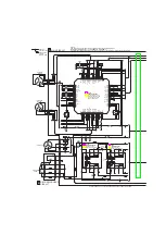
IC7111
MC68340PV: Host processor
Function Overview
IC7111 is the HOST microcontroller for the DVD set with the following
features:
– CPU32-MC68020 is a derived 32-bit Central Processor Unit
– 32 address lines, 16 data lines
– 2 DMA Controller for high-speed memory transfer
– 2 serial synchronous/asynchronous I/O interfaces (USART) for
communication with the Basic Engine (S2B)
– 2 independent counter/timers
– integrated drivers for TTL and ASIC, e.g. ELPD
– Clock frequency: 32.768MHz
– Clock frequency of USART interface: 3.6864MHz
IC7110
ispLSI 2032: High Density Programmable Logic device
Function Overview
This device serves as an expansion to the Chip Select outputs of Host
Processor IC7111. Dependent from the address inputs A[18:21] and
chip select inputs CS[0:2], it outputs the chip selects for the Digital
Stream Manager, Digital Video Processor, the MPEG decoder, the I
2
C-
bus controller and also the chip enable inputs for the FLASH and
EPROM memories.
It alters the system clock of 27MHz into the I
2
C-bus clock of 6.75MHz
(division by 4).
It also performs the interface (glue) between the CPU and DRAM
controller.
Pin name
Function
Description
A[23:0]
Address bus
Lower 24 bits of address bus
ASN
Address Strobe
Indicates that a valid address is on the address bus
BERRN
Bus Error
Indicates an erroneous bus operation is being attempted
BGACKN
Bus Grant Acknowledge
Indicates that an external device has assumed bus mastership
BGN
Bus Grant
Indicates that the current bus cycle is complete
BKPTN
Breakpoint
Signals a hardware breakpoint to the CPU32
BRN
Bus Request
Indicates that an external device requires bus mastership
CLKOUT
System Clock Out
Internal system clock
CS[3:0]N
Chip Select
Enables peripherals at programmed addresses
CTS1N, CTS2N
Clear To Send
Serial module clear to send inputs
D[15:0]
Data bus
16-bit data bus to transfer byte or word data
DACK1N, DACK2N
DMA Acknowledge
Output that signals an access during DMA
DONE1N, DONE2N
DMA Done
Bi-directional signal that indicates last transfer
DREQ1N, DREQ2N
DMA Request
Input that starts DMA process
DSACK[1:0]N
Data and Size Acknowledge
Provides asynchronous data transfers and dynamic bus sizing
DSN
Data Strobe
During a read cycle, DS indicates that an external device should place valid data on the data bus
EXTAL, XTAL
Crystal Oscillator
Connections for an external crystal
FREEZE
Freeze
Indicates that the CPU32 has acknowledged a breakpoint
HALTN
Halt
Suspends external bus activity


