47
English (US)
22. Bus signal
The pump supports serial communication via an RS-485 input.
The communication is carried out according to Grundfos bus
protocol, GENIbus protocol, and enables connection to a building
management system or another external control system.
Operating parameters, such as setpoint, operating mode, etc. can
be remote-set via the bus signal. At the same time, the pump can
provide status information about important parameters, such as
actual value of control parameter, input power, fault indications,
etc.
Contact Grundfos for further details.
23. Other bus standards
Grundfos offers various bus solutions with communication
according to other standards.
Contact Grundfos for further details.
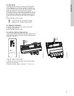
24. Indicator lights and signal relay
The operating condition of the pump is indicated by the green and
red indicator lights fitted on the pump control panel and inside the
terminal box. See fig.
46
.
Fig. 46
Position of indicator lights
In addition, the pump incorporates an output for a potential-free
signal via an internal relay.
For signal relay output values, see section
17.3.4 Signal relay
.
If a bus signal is used, the number of settings
available via the GO Remote will be reduced.
TM
0
2
8
513
0
304
TM
0
2
9
036
4
404
TM
0
3
9
063
3
307
Green Red
Green
Red
Green
Red


