Gravely 990014 Скачать руководство пользователя страница 11

5 - 11

5.1  ENGINE TROUBLESHOOTING

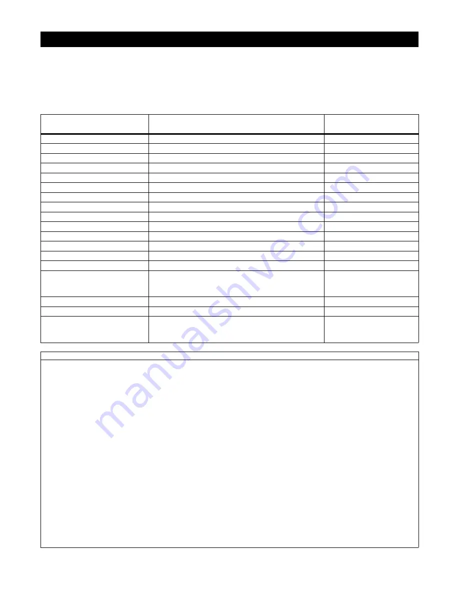
The following troubleshooting chart is to be used to 
isolate engine problems and give possible causes and 
corrective action responses.

The troubleshooting key is generic and can be used for 
several types of engines. Use only those possible 
causes and corrective actions that apply to the 
unit.

SECTION 5 - ENGINE

TROUBLE

POSSIBLE CAUSES

(Refer to Key Below)

CORRECTIVE ACTION

Black Exhaust

1, 20, 22, 25, 29, 31, 32, 33

repair or replace

Blue/White Exhaust

4, 20, 25, 31, 33, 34

repair or replace

Difficult Starting

1, 5, 7, 8, 9, 10, 20, 21, 22, 29, 31, 32, 33

repair or replace

Erratic Running

1, 7, 8, 9, 10, 20, 21, 23, 26, 29, 33, 59, 62

repair or replace

Excessive Fuel Consumption

1, 20, 22, 23, 25, 29, 31, 32, 33

repair or replace

Excessive Crankcase Pressure

25, 31, 33, 34, 45, 55

High Oil Pressure

4, 41

repair or replace

Knocking

22, 26, 29, 31, 33, 36, 46, 59

repair or replace

Loss of Power or System

1, 8, 10, 20, 21, 22, 23, 25, 26, 31, 32, 33

repair or replace

Low Cranking Power

2, 3, 4, 11

repair or replace

Low Oil Pressure

4, 36, 37, 39

repair or replace

Misfiring

10, 20, 25, 26, 28, 29, 32

repair or replace

Overheating

1, 19, 25,

repair or replace

Poor Compression

25, 28, 29, 31, 32, 33, 34,59,

repair or replace

Starts and Stops

1, 6, 10, 62

repair or replace
see electrical systems
see engine service manual

Vibration

20, 23, 25, 26, 29, 33, 45, 49

repair or replace

Will Not Crank

2, 11, 45

charge battery or replace

Will Not Start

1, 10, 62

repair or replace
see electrical systems
see engine service manual

TROUBLESHOOTING KEY

1

Restriction in air cleaner

22

Incorrect grade of fuel

43

Faulty suction pipe

2

Bad electrical connection

23

Sticking throttle/restricted movement

44

Choked oil filter

3

Faulty starter motor

24

Exhaust pipe restriction

45

Bad solenoid switch

4

Incorrect grade of lubricating oil

25

Leaking cylinder head gasket

46

Incorrect piston height

5

Low cranking speed

26

Overheating

47

Damaged fan

6

Fuel tank empty

27

Cold running

48

Faulty engine mounting

7

Controls not in correct operation 
position

28

Incorrect tappet adjustment

49

Incorrectly aligned flywheel and/or 
flywheel housing

8

Blocked fuel feed line

29

Sticking valves

50

Faulty thermostat

9

Faulty fuel lift pump

30

Incorrect high pressure pipes

51

Restriction in water jacket

10

Choked fuel filter

31

Worn cylinder bores

52

Loose fan belt

11

Battery capacity low

32

Pitted valves and seats

53

Choked radiator

12

Air in fuel system

33

Broken, worn or sticking piston ring(s)

54

Faulty water pump

13

Faulty fuel injection pump

34

Worn valve stems and guides

55

Choked breather pipe

14

Faulty fuel injectors or incorrect 
type

35

Restriction in air cleaner

56

Damaged valve stem oil deflector (if 
fitted)

15

Incorrect use of cold start 
equipment

36

Worn or damaged bearings

57

Coolant level too low

16

Faulty cold start equipment

37

Insufficient oil in sump

58

Blocked sump strainer

17

Broken fuel injection pump drive

38

Bad/defective oil temperature switch

59

Broken valve spring

18

Incorrect fuel pump timing

39

Oil pump worn

60

Exhaust or vacuum pipe leak

19

Incorrect valve timing

40

Pressure relief valve sticking open

61

Bad or defective water temperature 
switch

20

Poor compression

41

Pressure relief valve sticking closed

62

Bad spark plug(s)

21

Blocked fuel tank vent

42

Broken relief valve spring

Содержание 990014

Страница 1: ......

Страница 2: ...Arm 7 18 Section 8 Hydraulic System 8 19 8 1 Filter Change 8 19 8 2 Hydraulic Hoses 8 19 8 3 Hydraulic Tank 8 21 8 4 Lift Cylinder 8 21 8 5 Lift Pump 8 21 8 6 Pump Housing 8 21 8 7 Hydraulic Valve Pr...

Страница 3: ...UNAUTHORIZED REPLACEMENT PARTS Use only Gravely replacement parts The replacement of any part on this vehicle with anything other than a Gravely authorized replacement part may adversely affect the pe...

Страница 4: ...should be gathered before work is started Interrupting a job to locate tools or parts is a needless delay A list of required special tools has been included in this manual 2 7 CLEANING AND STORAGE IM...

Страница 5: ...ing unit ALWAYS remove key to prevent unauthorized use Never carry passengers on any part of unit Avoid uneven and rough terrain DO NOT operate near drop offs ditches or embankments Unit can suddenly...

Страница 6: ...Before maintenance adjustments or service except where specifically recommended shut off engine Allow hot parts to cool Keep unit free of dirt stones and other debris Clean up oil or fuel spills Spark...

Страница 7: ...w Filter 4 1 9 w Filter 3 50 1 7 w Filter Air Cleaner Dual Element With Pre Clean Screen Dual Element With Pre Clean Screen Dual Element With Pre Clean Screen Cooling Capacity N A N A N A Engine Oil T...

Страница 8: ...RAL MAINTENANCE ADJUSTMENTS 1 Handlebar 2 Choke Control 3 Mower Lift Lever 4 PTO Switch 5 Direction Control Pedal 6 Seat Adjuster 7 Hour Meter 8 Ignition Switch 9 Parking Brake Lever 10 Low Oil Pressu...

Страница 9: ...steners that are missing or damaged Tighten all nuts and bolts 4 5 LUBRICATION 1 Apply Stens Hi Temp Grease or equivalent to the lube fittings on idler pivots 2 Grease the pillow block idler pivot arm...

Страница 10: ...uld clear the footboard by 1 8 or less but not touch the footboard To adjust the pedal 1 Locate the adjustment rod assembly underneath the direction control pedal 2 Loosen the jam nut which locks the...

Страница 11: ...ct grade of fuel 43 Faulty suction pipe 2 Bad electrical connection 23 Sticking throttle restricted movement 44 Choked oil filter 3 Faulty starter motor 24 Exhaust pipe restriction 45 Bad solenoid swi...

Страница 12: ...from engine sheave NOTE Engine sheave will have to be removed prior to removing engine 6 Remove the engine sheave bolt and slide the sheave off the engine shaft 7 Remove the 4 engine mounting bolts Us...

Страница 13: ...ower belt from the unit s electric clutch pulley 5 Remove and save mower mounting hardware Detach mower 6 Replace belt cover on mower for storage Long mower belt may be stored under belt cover 6 3 ADJ...

Страница 14: ...the ignition key 2 Remove the belt guard from the support frame 3 Long Belt Loosen and remove the spring from the idler arm Remove the old belt 4 Short Belt When replacing the short belt the long bel...

Страница 15: ...angle 25 degrees removing equal amounts of material from each end to maintain proper blade balance New blades are balanced to within 1 3 inch ounces at factory DO NOT grind around corner at top of bla...

Страница 16: ...justment 7 2 DIRECTIONAL CONTROL PEDAL Removal and Installation 1 Disconnect the foot pedal adjustment linkage See Figure 13 2 Remove the E ring and washer on the right end of the pedal shaft Loosen t...

Страница 17: ...RAKE CABLE REPLACEMENT 1 Disconnect the cable at the brake arm weldment See Figure 16 Loosen the jam nuts on the brake cable brackets 2 Remove the cotter key from the clevis pin at the brake lever Rem...

Страница 18: ...arm assembly Separate the two by removing the E ring 3 Inspect and replace any worn or damaged parts 4 Reassemble in reverse order NOTE Be sure that when the brake lever is pulled back engaged that t...

Страница 19: ...lic tank and or transmission 2 Clean any filter where maintenance is to be performed prior to removing hoses to prevent system contamination Cap components if possible NOTE Place lift lever into float...

Страница 20: ...8 20 PF1643 Figure 17 1 Drive Coupler 2 Hydraulic Tank 3 Hydraulic Pump 4 Housing 1 2 3 4...

Страница 21: ...6 Reverse the disassembly procedure to reassemble NOTE Adjusting the lifting height of the mower deck may be necessary if a new hydraulic cylinder is installed Loosen the jam nut on the lifting rod e...

Страница 22: ...ncrease the pressure Rotate the adjusting screw counterclockwise to reduce the pressure Take care not to move the adjusting screw when tightening the jam nut 5 Reverse the disassembly procedure to rea...

Страница 23: ...ct the brake linkage at transmission 9 Remove the spring from the transmission bypass lever 10 Disconnect the forward reverse cable at the transmission control arm 11 Remove the two bolts securing the...

Страница 24: ...surfaces at reassembly The following tools are required for disassembly and reassembly of the transaxle 3 8 in Socket or End Wrench 1 in Socket or End Wrench Ratchet Wrench Torque Wrench 300 lb in 34...

Страница 25: ...using remove the ball bearing seal and thrust washer from the axle shaft The thrust washer may be in the axle housing NOTE The retaining ring remaining on the axle shaft need not be removed 8 To disas...

Страница 26: ...separate race securely in position 3 Then carefully pull the motor rotor assembly outward until the ball pistons are fully engaged in the grove located in the center of the separate race 4 Carefully r...

Страница 27: ...pistons are not dislodged from their bores IMPORTANT It is essential that the pump rotor assembly remain intact during handling as each ball piston is matched to its respective bore 20 Install a wide...

Страница 28: ...spection and cleaning Normal flushing should be all that is required for cleaning 9 6 TRANSAXLE REASSEMBLY Before reassembling the transaxle clean all parts and assemblies with clean solvent and blow...

Страница 29: ...old separately Class II generator and plate are not a matched set 6 Aligning the rotation arrow with the input rotation install the pump plate over the generator 7 Install the four cap screws in the p...

Страница 30: ...ated in the cover assembly 6 Install the cover assembly by carefully aligning it with the control shaft cam ring pivot dowel and pump rotor drive NOTE Two axle housing flange screws may be used to hel...

Страница 31: ...retaining ring in the axle housing 8 Lubricate and assemble the three planetary gears on the secondary carrier assembly 9 Aligning the splines install the secondary carrier assembly on the splined en...

Страница 32: ...following filter base internal filter and valve cover position metal side of filter toward housing and gasket port plate 28 Aligning the screw holes install 5 flange screws 29 Cross torque screws to 1...

Страница 33: ...in place flush with center hub opposite side of valve stem Installation 1 Pack rim and bearing with multi purpose grease Slide wheel on axle pack outside bearing with multi purpose grease and insert i...

Страница 34: ...aper to remove any rust or paint from the axle taper and wheel hub bore taper 1 Mark end of axle to indicate where cotter key hole is located 2 Install key and slide hub on axle 3 Install washer and c...

Страница 35: ...16 17 18 clean repair or replace Fuel Leak at Carburetor 5 7 17 repair or replace Engine Floods 5 15 17 repair or replace Will not idle 1 2 3 6 repair or replace Rich idle 1 6 14 repair or replace idl...

Страница 36: ...oved the clutch may have a tendency to slide off the pump shaft and could cause damage to the clutch or mower drive pulley 4 Remove the clutch retaining bolt and slide the clutch off the pump shaft 5...

Страница 37: ...e part would cost and the results may not be as good 12 2 ELECTRICAL MEASUREMENTS In many electrical circuits there is some visible effect which indicates that the circuit is functioning properly A sw...

Страница 38: ...nit 2 Remove all the vent caps from the battery and set the caps to one side 3 Take the electrolyte which should be 1 265 specific gravity at 80o F and fill each cell so that the electrolyte is level...

Страница 39: ...a time The electrolyte level should be at level indicated Use distilled water to fill each cell if needed Install and tighten each cap after checking IMPORTANT When distilled water is added to battery...

Страница 40: ...perate unit as normal to charge battery Storage The battery is a perishable item and it should be stored properly to obtain a long useful life Batteries not in use will self discharge If the battery w...

Страница 41: ...above test place the switch in the run position and check between each contact and ground metal case to be sure no terminals are grounded If the switch is operating properly there will be no continui...

Страница 42: ...to check for continuity 12 8 DIODES AND RECTIFIERS Diodes are solid state semiconductor devices They contain no moving parts and conduct current better in one direction than the other Diodes allow cur...

Страница 43: ...o 3 50 ohms proceed to Measure Clutch Current Draw Measure Clutch Current Draw 1 Turn engine off 2 Disconnect clutch wire connection 3 Select meter to check amps 10 amp scale 4 Connect one meter lead...

Страница 44: ...the above test 12 13 FUSE HOLDER 1 Use a VOM with the switch set in the ohm Rx1 position 2 Make a visual check of the fuse to determine that it is not burned out If the glass is clouded check with an...

Страница 45: ...NGAGED up position PTO Switch 01545600 Seat Switch 03654200 1 OPERATOR OFF SEAT 2 1 OPERATOR ON SEAT 2 Neutral Switch 050480 RUN 1 2 ENGAGED button out 1 2 NEUTRAL button in Brake Switch 03657100 BUTT...

Страница 46: ...N 000234 up See Service Letter 1071 Module can not be tested for correct operation Key Switch Off Run Start Red B 12 00 Vdc 12 00 Vdc 12 00 Vdc Purple A 12 00 Vdc 12 00 Vdc Red Violet S2 12 00 Vdc 12...

Страница 47: ...correct Brake Switch Off Run Start Yellow Red 12 00 Vdc Yellow Red 12 00 Vdc Switch Fwd Rev Neutral Off Run Start Brown Yellow 12 00 Vdc Brown Yellow 12 00 Vdc Seat Switch Off Run Start Lt Green 12 00...

Страница 48: ...K 87a 30 87 86 85 TIME DELAY MODULE A B C D E F P I N K OIL PRESSURE WHITE BLACK FUEL SOLENOID REGULATOR MAGNETO KILL OIL PRESSURE LIGHT B L U E W H I T E Y E L L O W R E D BLACK FORWARD NEUTRAL SWITC...

Страница 49: ...SOLENOID REGULATOR MAGNETO KILL OIL PRESSURE LIGHT B L U E W H I T E Y E L L O W R E D BLACK 1 2 BLACK PTO SWITCH 1 7 3 4 9 BLACK PTO CLUTCH PURPLE WHITE 1 2 A B M S1 G S2 PURPLE REVERSE NEUTRAL SWIT...

Страница 50: ...Gravely A division of Ariens Company 655 West Ryan Street P O Box 157 Brillion WI 54110 0157 920 756 2141 Fax 920 756 2407 www gravely com...

Отзывы: