66 310531
PrecisionFlo Control Interface Signals
The PrecisionFlo module is designed to be controlled by a robotic workcell or line control computer. This section
describes the interface between the line or cell control system and the PrecisionFlo module, and provides cable/pin
level information for the connections. For information about the connector pin-outs, see page 71 .
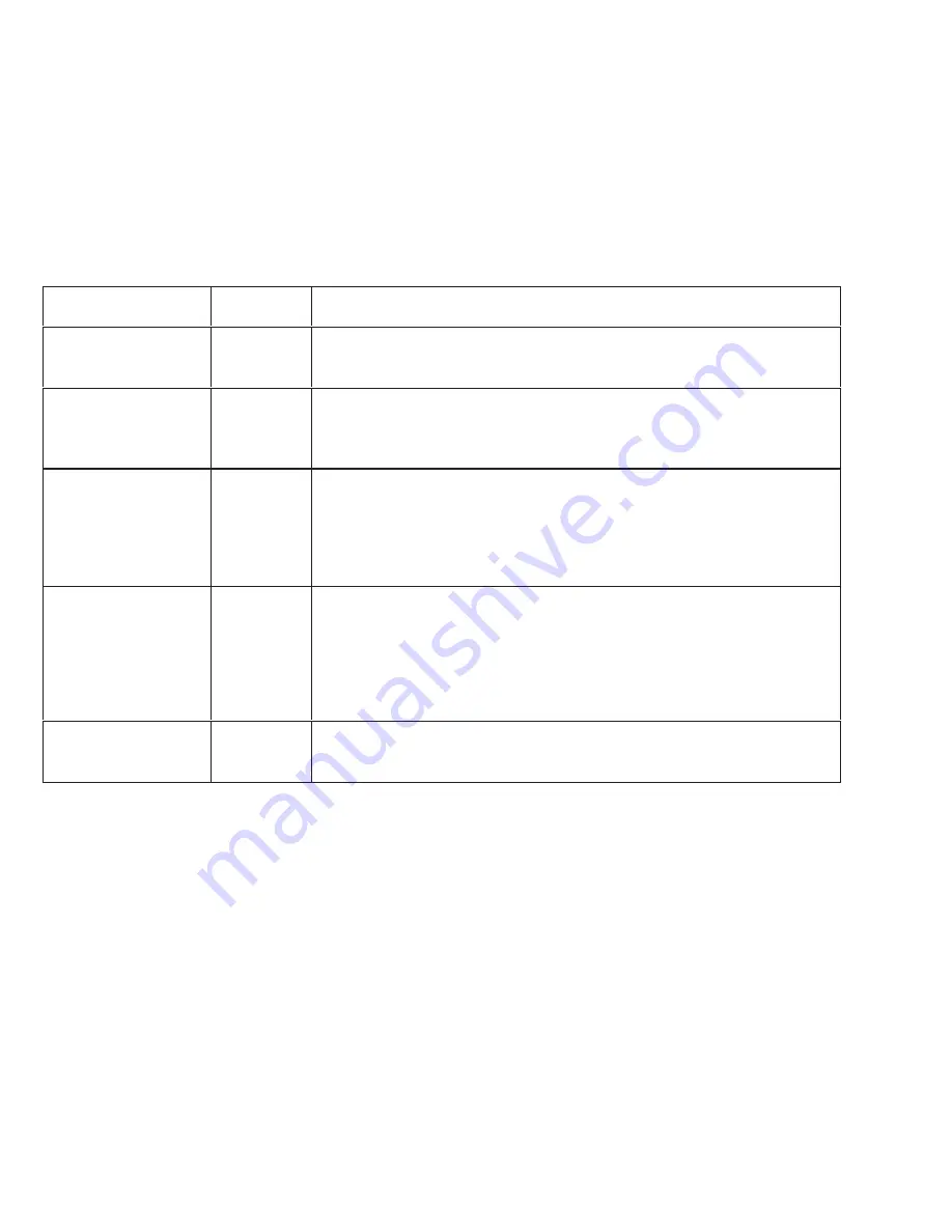
Digital Input
Signals sent from an external controller to the PrecisionFlo module.
Signal Name
Connector /
Pin
Signal Description
Dispense
I/O–D2
ON to dispense material in Automatic Mode.
OFF to stop dispensing.
Measure Volume
I/O–A3
When this signal goes HIGH, style bits are read and the measured volume
is reset. When the signal goes LOW, total volume for the cycle becomes
available. (Refer to Fig. 34 on page 56.)
Style Bit 0
Style Bit 1
Style Bit 2
Style Bit 3
Style Bit 4
Style Bit 5
I/O–D3
I/O–D7
I/O–D13
I/O–D5
I/O–A1
I/O–D8
Make the appropriate style bits HIGH to indicate the style bit code for the
current job before raising DISPENSE ENABLE. The style bits are used by
the PrecisionFlo module for SPC data collection. No compensation is
done based on this input. (Refer to figure 35, on page 56.)
Volume Request
I/O–A8
Make this signal HIGH, after DISPENSE ENABLE has been dropped, to
request volume reporting on the current job.
The PrecisionFlo module will provide the least significant 5 bits of volume
data and raise VOLUME VALID. VOLUME REQUEST can then be low-
ered and raised again, at which time the PrecisionFlo module will provide
the most significant 5 bits of volume data. (Refer to figure 37 on page 59.)
Fault Acknowledge
I/O–D1
Make this signal HIGH to acknowledge receipt of fault information by the
external controller and clear the fault/warning buffer. This signal will not
clear the fault/warning log displayed on the control pendant.


