GMC-I Gossen-Metrawatt GmbH
79
7
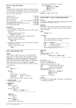
Adjusting the
SSP KONSTANTER
Warning!
The housing cover must be removed in order to balance the device and
voltage conducting components are thus exposed. For this reason, the
work described in this chapter may only be performed by trained
personnel who are familiar with the dangers involved!
Operating the device without connecting the protective conductor is
prohibited!
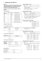
Balancing components:
Required measuring instruments:
a) For direct voltage measurement
b) For direct current measurement < 1 A
c) For direct current measurement > 1 A
Balancing conditions:
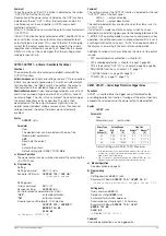
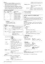
Balancing the I Monitor Zero-Point
Device settings:
OUTPUT ON; USET 2.00; ISET 2.00
Output:
Idle
– Connect digital voltmeter to I monitor (+) and AGND (–) at
the analog interface.
– Balance measured voltage U
I-Monitor
with R124 to:
– 5 mV < U
I-Monitor
< + 5 mV
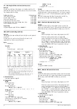
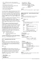
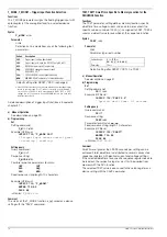
Balancing the I Monitor Final Value
Device settings:
OUTPUT ON; USET 2.00; ISET = I
nom
Output:
Shorted with shunt
– Connect digital voltmeter as described above and measure
voltage U
(-Monitor)
(must be approx. 10 V).
– Current I
s
at shunt R
s
is adjusted by turning R130, voltage
U
-Monitor
remains constant. Determine current I
s
by
measuring shunt voltage Us and balance to:
I
s
= I
nom
x U
-Monitor
/ 10 V
±
0.5%
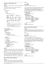
Balancing the Current Setpoint Zero-Point
Device settings:
OUTPUT ON; USET 2.00;
ISET = 0.012 where I
nom
= 12.5 A
= 0.025 where I
nom
= 25 A
= 0.050 where I
nom
= 50 A
= 0.080 where I
nom
= 75 A
= 0.100 where I
nom
= 100 A
= 0.160 where I
nom
= 150 A
Output: shorted with shunt or via ammeter
– Balance measured current I
s
with R529 to:
I
s
= ISET
±
20%
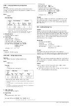
Balancing the Current Setpoint Final Value
Device settings:
OUTPUT ON; USET 2.00; ISET = I
nom
Output:
Shorted with shunt
– Measure current I
s
at shunt R
s
and balance with R524 to:
I
s
= 12.50 A ± 25 mA
where I
nom
= 12.5 A
= 25.00 A ± 45 mA
where I
nom
= 25 A
= 50.00 A ± 90 mA
where I
nom
= 50 A
= 75.00 A ± 210 mA
where I
nom
= 75 A
= 100.00 A ± 230 mA
where I
nom
= 100 A
= 150.00 A ± 410 mA
where I
nom
= 150 A
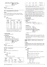
Balancing the Measured Current Zero-Point
Device settings:
OUTPUT ON; USET 2.00; ISET 2.00
Output:
Idle
– Balance the Iout value which appears at the right-hand
display with R669 to:
– 0.01
≤
Iout
≤
0.006
where I
nom
= 12.5 A
– 0.01
≤
Iout
≤
0.01
where I
nom
= 25 A
– 0.01
≤
Iout
≤
0.02
where I
nom
= 50 A
– 0.02
≤
Iout
≤
0.02
where I
nom
= 75 A
– 0.04
≤
Iout
≤
0.04
where I
nom
= 100 A
– 0.04
≤
Iout
≤
0.06
where I
nom
= 150 A
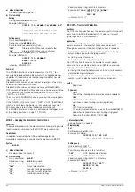
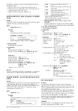
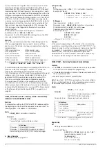
Trim
Potentiometers
On PCB:
Designation
Balancing Parameter
R124
FF
I Monitor 0
Current monitor zero-point
R130
FF
I Monitor max
Current monitor final value
R554
G
Uset 0
Voltage setpoint zero-point
R549
G
Uset max
Voltage setpoint final value
R529
G
Iset 0
Current setpoint zero-point
R524
G
Iset max
Current setpoint final value
R657
A
Uout 0
Measured voltage zero-point
R651
A
Uout max
Measured voltage final value
R669
A
lout 0
Measured current zero-point
R663a
A
lout max
Measured current final value
Digital Voltmeter:
Uncertainty
at Measured Value:
< 0.02 %
40 V / 52 V / 80 V
< 0.02 %
40 ... 150 mV
<0.2 mV
0 ... 10 mV
Input resistance > 1 M
Ω
Digital Multimeter:
Uncertainty
at Measured Value:
< 2 %
10 ... 200 mA
Voltage drop < 1 V
Digital Voltmeter
Same as a)
plus calibrated
shunt resistor:
Device Nominal Current
Shunt
12.5 A / 25 A
6 m
Ω
, 25 A
50 A / 75 A
2 m
Ω
, 75 A
100 A / 150 A
1 m
Ω
, 150 A
Overall measuring uncertainty at nominal current: < 0.07 %
Ambient temperature
23
±
2° C
Relative humidity
20 ... 80%
Mains voltage tolerance
±
3%
Warm-up time
10 minutes
Содержание 62 N Series
Страница 2: ...2 GMC IGossen MetrawattGmbH ...
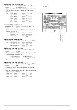
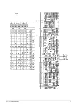
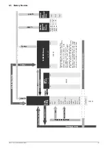
Страница 81: ...GMC I Gossen Metrawatt GmbH 81 PCB G ...
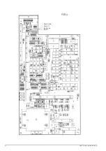
Страница 82: ...82 GMC I Gossen Metrawatt GmbH PCB A Uout max Uout 0 Iout max Iout 0 ...

