
70
GMC-I Gossen-Metrawatt GmbH
– USET
≥
OVSET (due to manual setting, programming
command, memory recall or Uset control signal to the analog
interface)
– Sensing leads with reversed polarity
– Interrupted output lead during sensing mode operation
– Interference from the power consumer
– Parallel connected voltage sources
– Dynamic output voltage overshooting
– Device malfunction or defect
Overvoltage protection triggering is indicated by means of the red
OVP LED, and results in immediate deactivation of the output
(OUTPUT OFF), as well as disabling of the HF power transmitter
and activation of the electronic sink for a period of approximately
350 ms (500 ms for 80 V device) in order to discharge the output
capacitor. In addition, bit 4 (OVPA) is set in event register A. Bit 4
remains set in status register A for as long as the trigger value is
exceeded.
As soon as the shutdown condition no longer exists, the power
output can be reactivated by means of OUTPUT ON.
The OVSET trigger value should be set at least 1 V higher that the
desired output voltage USET in order to prevent undesired
triggering of overvoltage protection resulting from overshooting
due to sudden output discharging (see values in 1.5.2, Electrical
Data).
The OVSET trigger value makes reference to the prevailing
voltage value between the output terminals of the SSP
KONSTANTER. This voltage is increased by the USET parameter
during sensing mode operation (remote sensing) by an amount
equal to voltage drop at the output leads. For this reason, the
above defined difference between OVSET and USET must be
correspondingly increased during sensing mode operation.
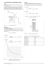
Overvoltage protection response time is less than 200 µs. Output
voltage generated by the device may exceed OVSET for the
duration of this response time. Maximum overshooting can be
approximately calculated as follows:
Δ
Uout = ISET [A] x 200 [µs] / C
out
[µF].
ISET
= selected current setpoint
C
out
= capacitance of the output capacitor
→
Subsequent discharging time for the output capacitor depends
upon load, and corresponds to the specified values for response
time at U
nom
→
1 Volt included in chapter 1.5.3.
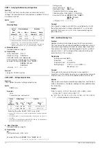
POUT? – Querying the Momentary Current Value
Functions
Momentary values for output voltage and output current are
acquired by means of the POUT function. These two quantities
are multiplied in order to arrive at the measured power value
POUT. Approximately 90 ms are required to acquire and process
the measured values.
Syntax
POUT?
Measuring Range:
Due to the fact that the UOUT and IOUT
measuring functions are utilized, the respective measuring ranges
apply for power measurements as well. If one or both of the
measured quantities UOUT and IOUT violate their respective
measuring ranges, the product of POUT (UOUT x IOUT) is
displayed as “–OL” or “+OL”, and “–99999.” or “+99999.” is
entered to the response string.
a) Manual Operation
b) Programming
Measured Value Query
Query command:
POU
T
?
Response string:
POUT
value
Parameter format
value
:
±nnnn.n
Fixed response string length: 12 characters
Example (HP Basic):
OUTPUT 712;"POUT?"
ENTER 712;A$
DISP A$
→
Display:
POUT +0662.7
Comment
See UOUT and IOUT measuring functions (
→
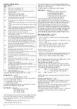
POWER_ON, POWER_ON? – Output Switching Status, Response
After Power On
Functions
The POWER_ON function determines the status of device
settings after mains power has been switched on.
Syntax
POWER_ON
status
Parameter
Status
One of the following text parameters can be selected for
specification of the desired
status
:
Default setting after RESET (*RST): unchanged
a) Manual Operation
b) Programming
Setting
Setting command:
POW
ER_ON
status
Example (HP Basic):
OUTPUT 712;"POWER_ON RST"
! Device is set to default
! settings after power-up.
Setting query
Query command:
POW
ER_ON
?
Response string:
POWER_ON
status
Possible response parameters for
status
:
"
RST
"
Default settings
"
RCL
"
Last used device settings
"
SBY
"
Last used device settings, deactivated output
Fixed response string length: 12 characters
Example (HP Basic):
OUTPUT 712;"POW?"
ENTER 712;A$
DISP A$
→
Display:
POWER_ON RST
Comment
The status of the POWER_ON function is not saved as a device
setting with the “SAVE” command.
Status
Description
RST
RESET:
Defined default settings are utilized
(
→
“Default Settings” in chapter 4.3.5, *RST)
RCL
RECALL:
Same settings as prior to last mains shutdown
SBY
STANDBY:
Same as RECALL except that the power
output remains deactivated (OUTPUT OFF)
Содержание 62 N Series
Страница 2: ...2 GMC IGossen MetrawattGmbH ...
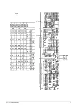
Страница 81: ...GMC I Gossen Metrawatt GmbH 81 PCB G ...
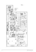
Страница 82: ...82 GMC I Gossen Metrawatt GmbH PCB A Uout max Uout 0 Iout max Iout 0 ...