


GMC-I Gossen-Metrawatt GmbH
15
b)
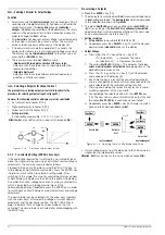
RS 232C Interface
Only two devices can be connected to each other with this
serial interface, namely a controller and the device to be
controlled.
If you intend to control several devices with a single controller,
the controller must be equipped with suitable interfaces. Most
controllers include two serial ports which are commonly
designated COM1 and COM2, and which are equipped with
25 or 9-pin subminiature plug connectors.
Suitable cable is available in various lengths from commercial
outlets for connecting the SSP-KONSTANTER to the
controller. Appropriate adapters are available as well, in the
event that your controller is equipped with a 9-pin plug
connector.
If you intend to fabricate the connector cable yourself, you will
need a 3-conductor shielded cable in order to establish the
connection as shown in Figure 1.5.2.
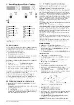
2.2 Switching the Instrument On
After the described preparations have been completed, the
device can be switched on.
•
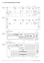
Press the mains switch [4] at the front panel until it snaps into
place in order to turn the device on.
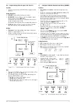
Power-Up Test
After switching the device on, the POWER lamp [5] lights up and
the fan is started. The microprocessor included in the device then
starts a power-up test. The following operations are performed
during the test routine (duration approximately 8 seconds):
– Reset all functional units (except battery-backed configurations
memory)
– ROM test
– RAM test
– Initialize computer interfaces if installed
– Ascertain device type
– Check the ADC timer
– Recall last settings if required
The READY lamp [22] blinks while this routine is running, and all
other LEDs and all digital display segments light up (display test).
If the device has been equipped with the “IEEE 488 – RS 232
computer interface” option, the selected IEC bus device address
then appears briefly at the display (example: “Addr 12”).
After successful completion of the self-test, the READY lamp is
continuously illuminated and the display is switched to measured
value indication for voltage (Uout) and current (Iout).
If this status is not achieved despite a correctly selected device
address (0 to 30), even after repeatedly switching the device on
and off with abbreviated self-test, the device is probably
defective. If this is the case, contact your local representative.
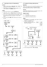
Abbreviated Power-Up Test
In order to shorten power-up time, or if problems occur with the
normal power-up test, an abbreviated power-up test can be
used:
•
With the device switched off, press and hold the <ENTER>
key.
•
Turn the mains switch on.
•
Release the <ENTER> key after approximately 1 second.
If this procedure is used, only essential initialization steps are run
during power-up.
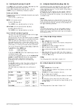
After initial power-up
, the device has the following basic
configuration:
•
Interface functions
Standard “pon” status
•
Device functions
– Output status
Inactive
– Voltage setpoint
0 V
– Current setpoint
0 A
– Voltage setting limit
Nominal output voltage
– Current setting limit
Nominal output current
– OVP trigger value
62.5 V (for 52 V models)
100 V (for 80 V models)
– Current limiting mode
Limiting without shutdown
– Shutdown delay
0 ms
– TRIGGER input
Inactive
– Min-Max measured value memory
Off
– Power ON mode
Reset configuration
– Manual operation
Enabled
– Memory contents
Deleted
The desired settings can be selected starting with this basic
configuration.
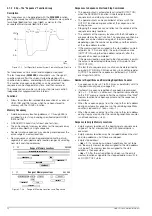
After a warm-up period of approximately 30 minutes, the
instrument operates at maximum accuracy.
When the device is powered up again at a later point in time
, active
device configuration depends upon the last setting selected for
the POWER_ON function (—> page 70):
– Default settings or
– Last used device settings or
– Last used device settings and inactive output
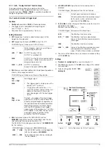
Power-Up with RESET
In order to assure that the connected power consumer is not
endangered by any previous device settings, the device can be
initialized with the “POWER_ON RST” function by pressing and
holding the <CE/LOCAL> key during the power-up routine.
In order to switch the device off
, activate the mains switch once
again. The device is then disconnected from mains power and the
output is deactivated. The last device configuration, as well as
any settings which have been saved to battery-backed
configurations memory, are retained.
Caution!
Avoid switching the device on and off in a rapid, repeated fashion. This
temporarily impairs the effectiveness of the inrush current limiting
function, and may result in a blown fuse.
Содержание 62 N Series
Страница 2: ...2 GMC IGossen MetrawattGmbH ...
Страница 81: ...GMC I Gossen Metrawatt GmbH 81 PCB G ...
Страница 82: ...82 GMC I Gossen Metrawatt GmbH PCB A Uout max Uout 0 Iout max Iout 0 ...