


14
GMC-I Gossen-Metrawatt GmbH
2
Initial Start-Up
2.1 Preparing for Operation
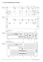
Note: Numbers in brackets refer to figures in chapter 3.
2.1.1
Installing the Optional IEEE 488 – RS 232C Interface
Module
Variant 1 or 2, see chapter 1.3.
Caution!
The device must be switched off when installing the interface module.
The interface module may be damaged by electrostatic discharge.
Observe guidelines for handling electrostatic sensitive devices. Do not
touch electrical contacts or PCB components.
1. Unscrew the cover plate at the left-hand side of the rear
housing panel.
2. Carefully insert the interface module into the open slot and
press it onto the plug connector.
3. Fasten the interface module with the screws taken from the
cover plate.
2.1.2
Installation to 19'' Device Racks
The SSP-KONSTANTER housing allows for use as a benchtop
instrument, as well as for installation to a 19'' rack.
The benchtop instrument can be quickly converted to a rack
mount device:
1. Unscrew the handles at the front.
2. Pull out the filler strips at the sides and replace them with the
included rack-mount fastening tabs.
3. Replace the front handles (if you prefer to leave the handles
out, turn M4 screws with a maximum length of 8 mm in to the
open threaded holes.)
4. Unscrew the feet from the bottom of the housing.
5. Save all loose parts for possible future use.
Attention!
The device must be attached to guide rails at both sides of the rack. The
guide rails, as well as the front panel mounting screws, are rack-specific
and must be procured from your rack supplier.
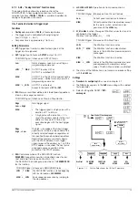
2.1.3
Connection to the Mains
Observe WARNING I!
Caution!
Before switching the SSP KONSTANTER on, it must be assured that
available mains power complies with the supply power values specified
at the mains connection on the back of the device.
– Series 62 N (500 W, 1000 W) :
These devices require 230 V supply power and are connected
to a mains outlet with earthing contact with the included power
cable via the mains connector plug [35] at the rear panel.
– Series 64 N (2000 W, 3000 W):
WARNING!
These devices may only be connected to mains supply power
by a qualified electrician.
These devices require 3-phase 120/400 V supply power with
neutral and phase conductors (3 L + N + PE).
A 5-conductor power cable with a minimum wire cross-section
of 1.5 square mm is required for connection to mains supply
power, and is connected to the terminal block [35] at the rear
panel:
L1:
Phase
L2: Phase
L3: Phase
N: Neutral
conductor
PE: Protective
conductor
The cable must be secured with the cable clamp [38] for
reliable strain relief.
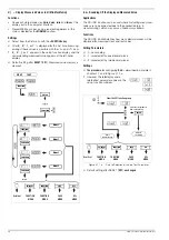
2.1.4
Connecting Power Consumers
The output leads are connected to the output terminal bars [33] at
the rear panel by means of ring-type cable lugs. The terminal bars
are equipped with drill holes for M8 screws to this end. 4 mm drill
holes are included as well, which can be used for connecting
measurement cables, ground cables or cable shields.
Connection:
•
Remove the safety cap.
•
Connect the output leads to the terminal bars with suitable
screws and washers.
•
Make sure that the utilized cables have an adequate cross-
section, and that polarity is not reversed. It is advisable to twist
the output leads and to identify polarity at both ends.
•
Avoid exerting of force at the terminal bars.
•
Arrange the leads such that they can be fed through the
opening in the safety cap.
•
Snap the safety cap back into place.
In order to be able to take advantage of highly constant output
voltage at the consumer even if long leads are used, sensing
leads can be used to compensate for voltage drops within the
output leads (
→
2.1.5
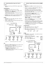
Connection to Computer Interfaces
If the device is used within computer controlled systems, one of
the two connections described below must be established via the
optional interface.
Comment
The device cannot be remote controlled via both interfaces
simultaneously. The interface which first initiates action after
mains power has been switched on is activated, and the other
remains inactive.
In order to assure that existing bus activity is not interfered with,
all affected devices should be switched off while establishing the
bus connection.
Both interfaces are equipped with a common ground (GND), and
are electrically isolated from the output in accordance with
specified electrical safety regulations.
Connection
Configure the interface as described in chapter 4.7.4 before
connecting.
a)
IEC Bus
Up to 15 IEC bus controlled devices (including controllers) can
be interconnected to create a system.
These devices are connected to the bus with suitable,
commercially available cables with 24-pin plug connectors.
If your IEC bus system is equipped with the previously
common 25-pin subminiature plug connectors, you will need a
suitable adapter cable.
Both cable types are available as accessories (see last page).
In order to assure reliable data transmission, cable length
between devices should not exceed 2 m, and overall length
should not exceed 15 m.
Double shielded connector cable is recommended if bus
devices are operated in proximity to strong sources of
interference or their power cables.
Содержание 62 N Series
Страница 2: ...2 GMC IGossen MetrawattGmbH ...
Страница 81: ...GMC I Gossen Metrawatt GmbH 81 PCB G ...
Страница 82: ...82 GMC I Gossen Metrawatt GmbH PCB A Uout max Uout 0 Iout max Iout 0 ...