


GMC-I Gossen-Metrawatt GmbH
19
3. Acknowledge and execute the selected setting
by pressing the <ENTER> key.
→
Both displays return to default values Uout and Iout.
If the rotary knobs or other function keys are activated, the
function menu is exited and settings remain unchanged.
Exceptions:
<OUTPUT> is autonomously active.
<RESOL> remains active for numeric parameters, and is
otherwise inactive.
Function parameters which do not blink in their entirety are
accepted without acknowledging with <ENTER>.
The last open menu appears when the functions menu is
reopened.
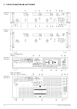
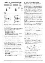
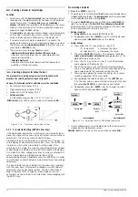
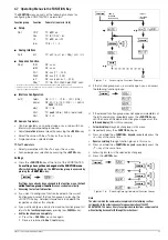
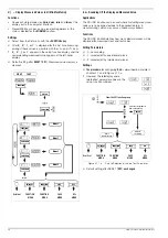
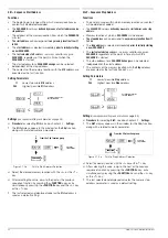
[19] Resolution selection key <RESOL>
This key can be used to vary step size (setting resolution) for
device functions with numeric parameter settings, whose
displayed values can be increased or decreased with the
rotary knobs, or the <
↑
> and <
↓
> keys.
The decimal place to be increased or decreased blinks.
Blinking can be positioned at any one of the three lowest
(right-most) decimal places by repeatedly pressing the
<RESOL> key, thus allowing for the selection of fine,
medium or coarse setting resolution.
A different resolution can be selected for the left and right-
hand displays, and settings remain valid until a new
resolution is selected, or until the device configuration is
reset. Manual resolution adjustment after reset (*RST): fine
(right-most decimal place)
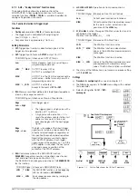
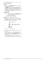
[20] Save key <SAVE>
and
[21] Recall key <RCL>
The memory function is controlled with these two keys (
→
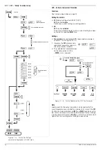
[22] <ENTER> key
The parameter value selected for a given device function
setting is acknowledged and executed by pressing this key.
[23] <CE/LOCAL> key
This key has several functions:
1. Abort an operation
If the <CE/LOCAL> key is activated while a device function
is displayed for adjustment, the display returns to its default
value and no change is made to the selected device setting.
2. Switch from remote to local control
If the device is being remote controlled via one of the
computer interfaces (REMOTE LED illuminated), all of the
control panel elements are disabled except for the mains
switch and the <CE/LOCAL> key. The device can be
returned to manual operation and the control panel elements
can once again be enabled by pressing the <CE/LOCAL>
key (
→
REMOTE LED off), without causing any changes to
current device settings.
If the device is being controlled via the IEC bus, the
<CE/LOCAL> key can be disabled with the LOCAL
LOCKOUT command, making key-operated return to
manual mode operation impossible.
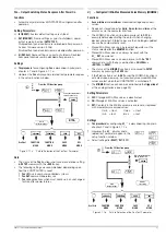
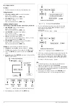
3. RST – reset device settings (RESET)
The reset command is triggered by pressing and holding the
<CE/LOCAL> key and simultaneously activating the
<ENTER> key. This command returns most device functions
to their predefined default settings. Default settings are
described in chapter 4.16 and on page 62.
4. Disabling front panel controls
By pressing and holding the <CE/LOCAL> key and
simultaneously activating the <RCL> key, all control panel
elements are disabled except for the mains switch and the
<CE/LOCAL> key, and the LOCAL LOCKED LED lights up.
Disabling front panel controls prevents unauthorized or
inadvertent adjustment of device settings.
In order to reactivate the controls, the <CE/LOCAL> key
must be pressed and held for at least 4 seconds (
→
LOCAL
LOCKED LED off).
The <CE/LOCAL> key can also be disabled by applying a
signal to the TRIGGER input at the analog interface and
selecting the appropriate setting for the T_MODE function,
thus preventing manual reactivation of the front panel
controls.
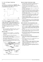
[24] READY indicator
Indication of ready for operation:
– LED on: The device is ready for operation and the controls
are enabled.
– Blinking LED: The device is performing a self-test and
cannot be operated at the moment, or the SEQUENCE
mode is active (
→
– LED off: The device is not ready for operation.
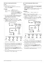
[25] Interface status displays: REMOTE, ADDR and SRQ
Indication of computer interface operating status:
– REMOTE LED on: Device is being remote controlled, front
panel controls are disabled.
– ADDR LED on: The device has been addressed and is
receiving or transmitting data (applies to IEC bus operation
only).
– SRQ LED on: The device is transmitting a service request
(applies to IEC bus operation only).
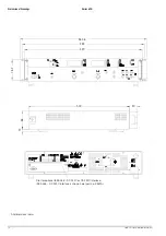
[26] Device serial plate
For identification of the device
Contains particulars regarding the manufacturer, device
type, type designation, order number, serial number,
hardware revision level and power consumption.
[27] IEC 625 bus interface
For remote control of device functions via the IEC 625 bus
(= IEEE 488 bus) (
→
Caution!
The electrical contacts of this interface are connected to
components which may be damaged by electrostatic discharge.
Ground yourself by grasping the housing before touching these
contacts!
[28]
—
[29]
—
[30] RS 232C interface
For controlling device functions via the RS 232C serial port
(
→
Caution!
The electrical contacts of this interface are connected to
components which may be damaged by electrostatic discharge.
Ground yourself by grasping the housing before touching these
contacts!
[31] Ground terminal
The output or cable shields can be grounded here if shielded
output cables or control cables for the analog interface are
used.
The ground terminal is connected to the housing and the
earthing contact at the mains connection.
Содержание 62 N Series
Страница 2: ...2 GMC IGossen MetrawattGmbH ...
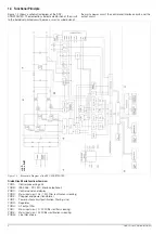
Страница 81: ...GMC I Gossen Metrawatt GmbH 81 PCB G ...
Страница 82: ...82 GMC I Gossen Metrawatt GmbH PCB A Uout max Uout 0 Iout max Iout 0 ...