
60
GMC-I Gossen-Metrawatt GmbH
6.4 Description
All setting, query, register management and interface commands
are listed alphabetically in the following pages (*A..., *B..., *C...,
..., A..., B..., C..., ...). In addition to the application-specific
overview in the previous chapter, setting, query and status
commands are included in the appendix arranged according to
function.
*CLS – Clear Status
Functions
The *CLS command Clears all event registers and the status byte
register, except for the MAV bit. Any existing service requests are
cancelled.
Addressing status
Unchanged
Input and output buffers
Unchanged
Service request SRQ
Cleared
Status byte register STB
Cleared except for MAV bit
Event registers ESR, ERA, ERB
Cleared
Enable registers ESE, ERAE, ERBE, SRE, PRE
Unchanged
Set or stored parameters
Unchanged
Programming
Programming example (HP Basic):
OUTPUT 712; "*CLS"
*DDT, *DDT? – Define Device Trigger
Functions
A list of commands including up to 80 characters can be entered
to a register with the define device trigger command. The
command list is executed after receiving the *TRG device
message or the IEC bus command GET (GROUP EXECUTE
TRIGGER).
Programming
a) Setting
Syntax
*DDT
command
[/
command
][/
command
] ...
|—max. 80 char.—–|
Parameter
Command
All specified device messages (setting and query commands)
are allowable except for the *TRG command.
Default parameter according to power-on or *RST:
DDT register cleared
A slash (/) must be used as the delineating character between
commands in the DDT string instead of a semicolon (;).
Programming example (HP Basic):
OUTPUT 712;"*DDT USET 10/ISET 5.6/OUT ON"
OUTPUT 712;"USET 0"
:
OUTPUT 712;"*TRG"
OUTPUT 712;"USET?; ISET?"
ENTER 712;A$
DISP A$
→
Display: USET +010.000;ISET +005.600
b) Query
The content of the DDT register can be read out with the
*DDT? query command.
The delineating slashes (/) appear once again as semicolons (;)
in the response string.
Query command:
*DDT?
Sample response string:
USET 10;ISET 5.6;OUT ON
Maximum response string length: 80 characters
Comment
In order to prevent the generation of query errors, a blank (space)
is returned if the DDT register is empty.
The *TRG command may not be entered to the DDT command
string. If it were entered it would set bit 4 (EXE, execution error) in
the standard event register, and bit 3 (DDTE, define device trigger
error) in event register B.
If the maximum DDT string length is exceeded, all characters in
excess of the allowable number are ignored and an execution
error message is generated.
The received command list is not checked for correct syntax and
limit values until the trigger command is received.
If an execution error occurs, the DDT register can be read out with
the *DDT? command, but its content cannot be executed
(execution error message is generated again).
The DDT register is not changed or cleared when the trigger
command is executed.
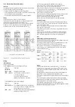
*ESE, *ESE?, ERAE, ERAE?, ERBE, ERBE?, *SRE, *SRE?, *PRE, *PRE? –
Enable Registers
Functions
The enable registers determine which bit(s) from the
corresponding event or status byte register is/are capable of
influencing the respective group message. The respective group
message remains set (1 = TRUE), as long as at least one bit
which has been enabled to this end has a status of TRUE.
This allows for selective enabling or disabling of an SRQ and/or
the individual status message “IST” due to an occurred event
(masking).
Programming
The device is furnished with five enable registers. They can be
written to and read separately. Queries, the *CLS command and
device functions do not cause any changes to the contents of
these registers. The registers can be cleared by entering a value
of “0” (e.g. *ESE 0). The enable registers are non-volatile, and are
only cleared by means of device shutdown if the non-volatile PSC
flag is set to 1.
n
= decimal equivalent of register content (0
≤
n
≤
255).
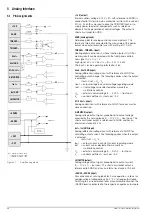
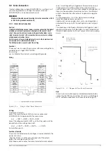
*ESR?, ERA?, ERB? – Event Register Query
Functions
The event registers provide information concerning events which
have occurred within the device since the last query. They acquire
and save status changes which have occurred for specific device
functions. The corresponding bit is set to 1 in the event register (1
= TRUE), when the respective function status
– is changed from FALSE to TRUE (for input
—
|
—
) or
– is changed from TRUE to FALSE (for input
—
\
—
).
For example, the CME command error bit is set in the ESR event
standard register upon receipt of an incorrect programming
command. This bit remains set, even if correct commands are
subsequently transmitted to the device. The CME bit is not reset
until the ESR register is queried.
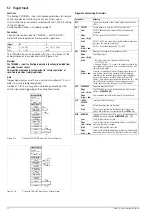
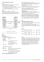
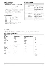
Designation
Setting Command
Query Command
Event standard enable register (ESE)
*ESE
n
*ESE?
Event enable register A (ERAE)
ERAE
n
ERAE?
Event enable register B (ERBE)
ERBE
n
ERBE?
Service request enable register (SRE)
*SRE
n
*SRE?
Parallel poll enable register (PRE)
*PRE
n
*PRE?
Содержание 62 N Series
Страница 2: ...2 GMC IGossen MetrawattGmbH ...
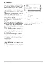
Страница 81: ...GMC I Gossen Metrawatt GmbH 81 PCB G ...
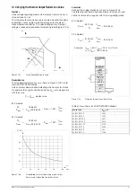
Страница 82: ...82 GMC I Gossen Metrawatt GmbH PCB A Uout max Uout 0 Iout max Iout 0 ...