90
GMC-I Gossen-Metrawatt GmbH
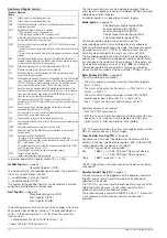
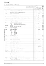
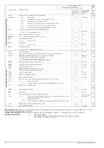
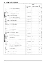
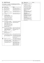
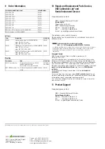
8.6 System Messages
Error messages may appear at the digital display immediately
after the device is switched on, or after triggering certain functions
manually or via remote control .
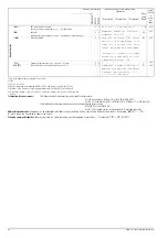
Code
Meaning / Cause
Remedy
Err 1
ROM checksum error .
ROM memory test failed.
The device must be tested at a service
center and repaired if necessary.
Err 2
RAM write/read error.
RAM memory test failed.
The device must be tested at a service
center and repaired if necessary.
Err 3
Write/read error.
Initialization of the IEC bus interface
failed.
The device must be tested at a service
center and repaired if necessary.
Err 5
An unspecified self-test sub-function
has failed.
The device must be tested at a service
center and repaired if necessary.
Err 7
Serial interface disabled,
impermissible configuration, e.g. 8DB,
PE, 2SB, or 7DB, PN, 1SB.
The error message is displayed during
the power-up routine, or under the
“BUS” menu item after each entry.
Err 20
Attempted delete and insert outside of
the defined memory range (from start
to stop address).
Err 21
Error message during SEQUENCE
function operation, or after RECALL:
The (next) voltage or current setpoint
value to be recalled from the
SEQUENCE memory is higher than the
respective limit value (USET > ULIM or
ISET > ILIM). For this reason, memory
recall cannot be executed. The
SEQUENCE is aborted.
Check the contents of the SEQUENCE
to be executed, and coordinate
setpoints and limit values.
Err 22
Error message after SEQUENCE GO:
No executable values exist within the
storage area defined by the START
and STOP addresses for the
SEQUENCE. The SEQUENCE cannot
be started.
Check the selected START and STOP
addresses, as well as the contents
(USET, ISET and TSET) of the memory
locations defined by these
parameters.
Err 24
Attempted recall of an invalid value
(remote: *RCL xxx, where
011
≤
xxx
≤
255).
Err 25
Error message after OUTPUT ON:
Activation of the output is disabled by
an OUTPUT OFF signal at the trigger
input of the analog interface.
In order to activate the output, either
the trigger control signal must be set
to low, or the effect of the trigger input
must be set to another function, after
which the OUTPUT ON command
must be re-executed.
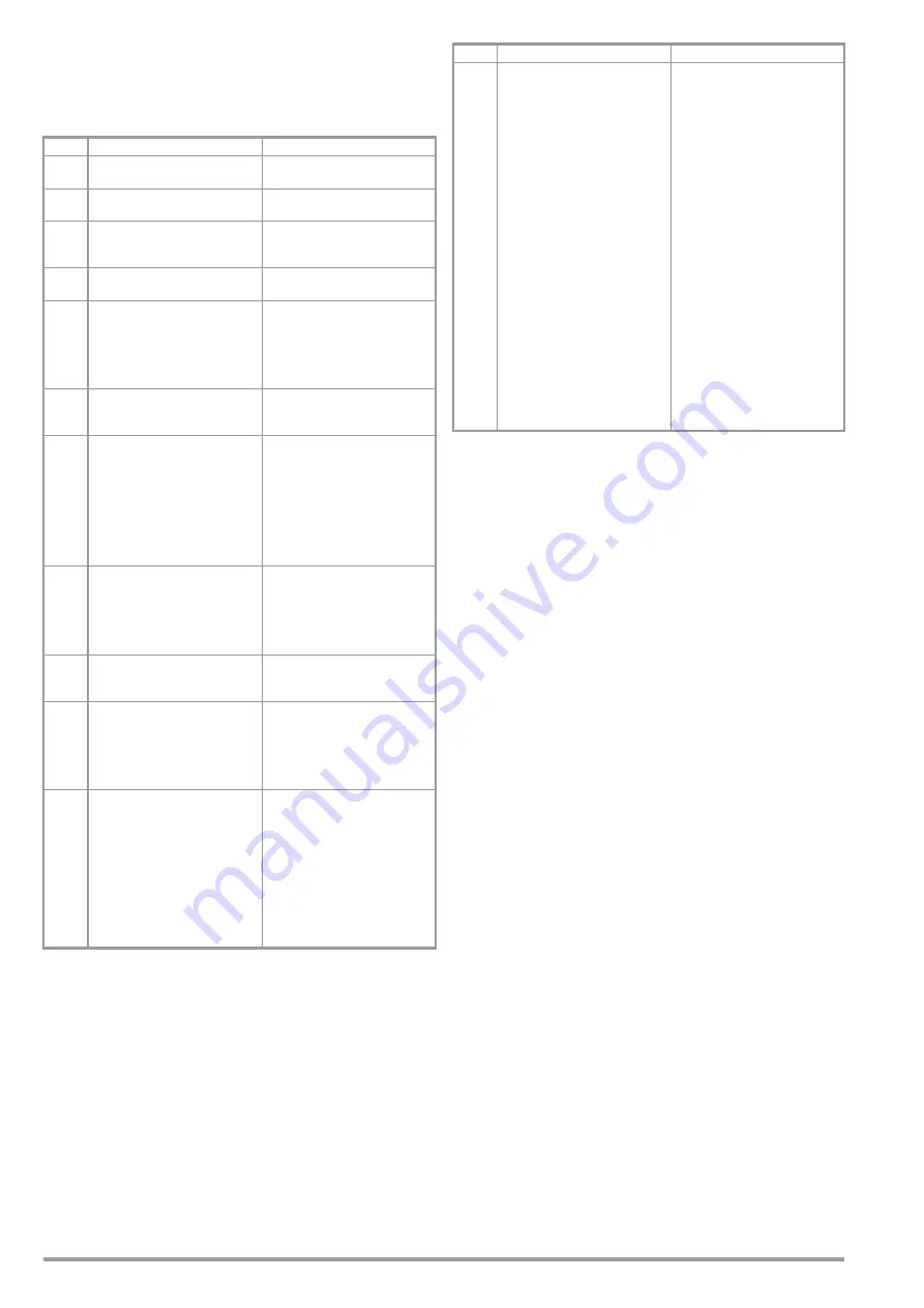
LInE
FAIL
Error message for series 64 N
devices:
At least one of the three supply power
phases has failed. The output is
deactivated immediately after this
message is generated, and the device
is disabled against further use.
Switch the device off and inspect for
correct connection of supply power at
the mains terminals at the back of the
device, as well as for correct fuse
ratings and intact fuses.
Due to the fact that the device us
capable of handling the failure of a
single phase without affecting
operation, this message does not
appear until after the failure has
persisted for several seconds.
+OL or
–OL
Display indicating measuring function
over-ranging:
If a measured output voltage UOUT or
output current IOUT violates the
specified range (—> chapter 1.5.3),
+OL or –OL appears at the display.
The appearance of this message
always indicates that the specified
limit values for output voltage or
current have been violated.
Examples:
UOUT indOL:
e.g. caused by
overdriving output voltage with an
analog control signal applied to the
analog interface.
UOUT indicates –OL:
due to
incorrectly connected sensing leads.
IOUT indOL:
e.g. caused by
overdriving output current with an
analog control signal applied to the
analog interface.
POUT indOL:
Since POUT is
calculated by multiplying UOUT and
IOUT, it can be assumed that one of
the above listed causes is responsible
for this message.
Code
Meaning / Cause
Remedy
Содержание 62 N Series
Страница 2: ...2 GMC IGossen MetrawattGmbH ...
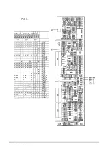
Страница 81: ...GMC I Gossen Metrawatt GmbH 81 PCB G ...
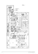
Страница 82: ...82 GMC I Gossen Metrawatt GmbH PCB A Uout max Uout 0 Iout max Iout 0 ...