6.2 LITER DIESEL 6A7-15
*
Inside of the cover for wear that would permit oil to
leak past the ends of the gears. The pump gears,
cover, and body are not serviced separately. If the
parts are damaged or worn, replace the entire oil
pump assembly.
Pickup screen and pipe for damage to the screen,
pipe or relief grommet.
A ssem ble
1. Pressure regulator valve and related parts.
2. Idler gear and drive gear with shaft. Align the marks
made during disassembly.
3. Oil pump cover.
4. Oil pump cover screws.
L9
Inspect
Oil pump operation. Turn the drive shaft by hand
and check for smooth rotation.
VALVE TRAIN COMPONENTS
*
Clean
Parts in solvent. Blow dry with compressed air.
Make sure the oil passages in the pushrods are
clear.
D isassem ble (Fig ure 19)
1. Rocker arm retainers (160).
• Insert a screwdriver into the rocker arm shaft
bore and break off the end of the retainers.
• Pull the rocker arm retainers out with pliers
(figure 19).
2. Rocker arms from the rocker arm shaft. Mark the
rocker arms so they can be returned to their original
locations at assembly.
1?
Inspect
— Rocker arms and shafts at their mating surfaces.
These surfaces should be smooth and free from
scoring or other damage.
— Rocker arm areas which contact the valve stems
and the sockets which contact the pushrods. These
areas should be smooth and free of damage and
wear.
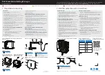
170. V a lv e K e e p e r
171. R o t a t o r
172. S h i e l d
173. O - R i n g S e a l
174. S e a l
175. V a l v e S p r i n g a n d
D a m p e r
k
^-175
174
1
7 0 ' ' '
175
176. S h i m
177. E x h a u s t V a lv e
178. C a p
179. I n t a k e V a lv e
170 .,78172173
176
F-05727
*
Figure 20— Valves and C om p o n e n ts
Pushrods for bending. Roll the pushrod on a flat
s u rfa ce to d e te rm in e if it is bent. R eplace if
necessary.
Ends of the pushrods for scoring or roughness.
Hydraulic lifter guide plates and clam ps for damage.
A ssem ble
Rocker arms to the rocker arm shaft. Used rocker
arms must be returned to their original locations.
Im p o rtan t
• Lubricate the rocker arms with engine oil
before installing.
2. New rocker arm retainers (160).
• Center the rocker arms on the corresponding
holes in the rocker arm shaft.
• Install the retainers with a drift of at least 13
mm (1/
2
-inch) diameter.
HYDRAULIC LIFTERS
Refer to GENERAL ENGINE MECHANICAL (SEC. 6A).
Im p o rtan t
• Some engines will have both standard 0.010-inch
oversize hydraulic lifters. The oversize lifter will have
a “ 10” etched on the side. The block w ill be
stamped “ O.S.” on the cast pad adjacent to the
lifter bore and on the top rail of the cylinder case
above the lifter bore.
CYLINDER HEAD
❖
D isassem ble (Figures 20, 21, and 22)
Tool Required:
J 8062 Valve Spring Compressor
1. Valve keepers (170).
• C om press the valve sp rin g s w ith J 8062
(figure 21).
• Remove the valve keepers.
• Remove J 8062.
Содержание 1989 Light Duty Truck
Страница 1: ...vr V Light Duty Truck Unit Repair Manual...
Страница 2: ......
Страница 11: ...GENERAL INFORMATION OA 5 Figure 8 RV Models...
Страница 13: ...GENERAL INFORMATION OA 7 Figure 11 ST Models...
Страница 18: ......
Страница 44: ......
Страница 76: ...1B3 18 R 4 AIR CONDITIONING COMPRESSOR N...
Страница 114: ......
Страница 162: ......
Страница 176: ...4B3 14 91 2 INCH RING GEAR...
Страница 192: ...4B5 4 DANA REAR AXLES Figure 4 Spreading the Differential Case Figure 7 Removing the Ring Gear...
Страница 218: ......
Страница 220: ...4B6 2 12 INCH RING GEAR ROCKWELL F 04734 Figure 1 Rear Axle Components...
Страница 229: ...12 INCH RING GEAR ROCKWELL 4B6 11 SPECIAL TOOLS Special Tools...
Страница 230: ...4B6 12 12 INCH RING...
Страница 240: ...4B7 10 LOCKING DIFFERENTIALS SPECIAL TOOLS Special Tools...
Страница 258: ...4C2 4 93 4 INCH RING GEAR FRONT AXLE F 04756 Figure 4 Spreading the Differential Case Figure 7 Removing the Ring Gear...
Страница 259: ...93 4 INCH RING GEAR FRONT AXLE 4C2 5 Figure 10 Removing the Pinion Gears Figure 13 Pinion Flange Removal...
Страница 260: ...4C2 6 93 4 INCH RING GEAR FRONT AXLE Figure 16 Removing the Pinion Inner Bearing...
Страница 273: ...T TRUCK FRONT AXLE 4C3 3 F 05785 Figure 1 Axle Components...
Страница 291: ...K TRUCK FRONT AXLE 4C4 3 Figure 1 Front Axle Com ponents K 15 25 Models...
Страница 293: ...K TRUCK FRONT AXLE 4C4 5 Figure 3 Front Axle Com ponents K35 Models...
Страница 318: ...C4 30 K TRUCK FBOHT AXLE...
Страница 334: ......
Страница 361: ...2 5 LITER L4 ENGINE 6A1 5 Figure 3 Cylinder Head Manifolds and Components...
Страница 363: ...2 5 LITER L4 ENGINE 6A1 7 F 05715 Figure 5 Block and Components...
Страница 395: ...2 8 LITER V 6 6A2 3 Figure 1 Engine Lubrication Diagram...
Страница 396: ...6A2 4 2 8 LITER V 6 Figure 2 Engine Lubrication Diagram...
Страница 424: ...6A2 32 2 8 LITER V 6...
Страница 427: ...I 4 3 LITER V 6 6A3 3 Figure 1 Engine Lubrication Diagram B 07857...
Страница 446: ...6A3 22 4 3 LITER V 6 F 04488 A Forward B Sealant 70 Gasket 71 R einforcem ent Figure 37 Oil Pan Installation...
Страница 451: ...4 3 LITER V 6 6A3 27 SPECIFICATIONS ENGINE SPECIFICATIONS F 6344...
Страница 457: ...4 8 LITER L6 6A4 3 Figure 2 Lubrication Diagram Front View...
Страница 459: ...4 8 LITER L6 6A4 5 11 12 13 9 15 sT iM V le JsJ 1 1 K V 7 B 07997 Figure 4 Cylinder Head Manifolds and Components...
Страница 460: ...6A4 6 4 8 LITER L6 C 1 107 112 fK 108 3 109 165 129 B 05056 Figure 5 Block and Components...
Страница 490: ...Ml...
Страница 493: ...V8 ENGINE 6A5 3 Figure 1 Lubrication Diagram 5 0L and 5 7L Engines...
Страница 494: ...6A5 4 V8 ENGINE Figure 2 Lubrication Diagram 5 0L and 5 7L Engines...
Страница 530: ...6A5 40 V8 ENGINE Figure 81 Exhaust Manifold 7 4L Engines Figure 82 Water Pumps and Components...
Страница 571: ...6 2 LITER DIESEL 6A7 35 Figure 58 Vacuum Pump Installed...
Страница 576: ......
Страница 582: ...6C1 6 MODEL 1MEF CARBURETOR Figure 9 Monojet Model 1MEF...
Страница 604: ...6C2 6 MODEL M4MEF CARBURETOR Figure 9 Model M4MEF...
Страница 640: ...6C4 8 MODEL 700 THROTTLE BODY...
Страница 652: ...nmm...
Страница 672: ......
Страница 693: ...DISTRIBUTORS 6D5 13 Figure 27 Testing the Pickup Coil Figure 28 Testing the Ignition Coil...
Страница 696: ......
Страница 698: ...7A1 2 700 R4 AUTOMATIC TRANSMISSION Figure 1 Case and External Parts J H 0 0 5 3 7 0 0 R 4 R 2...
Страница 707: ...700 R4 AUTOMATIC TRANSMISSION 7A1 11 682 A JH 0 0 7 1 700R4 R2 Figure 20 Transmission Internal Parts...
Страница 745: ...700 R4 AUTOMATIC TRANSMISSION 7A1 49...
Страница 762: ...7A2 2 400 475 AUTOMATIC TRANSMISSION Figure 1 Case and External Parts H H 0021 400 R 3...
Страница 773: ...400 475 AUTOMATIC TRANSMISSION 7A2 13 Figure 29 Internal Parts H H 0 0 4 3 4 0 0 R 2...
Страница 797: ...400 475 AUTOMATIC TRANSMISSION 7A2 37 Figure 93 Control Valve Assem bly...
Страница 803: ...400 475 AUTOMATIC TRANSMISSION 7A2 43 Figure 104 Bushing Replacement Procedure...
Страница 808: ...J c I i sal...
Страница 838: ......
Страница 840: ......
Страница 842: ......
Страница 850: ...7B1 12 HM 290 MANUAL TRANSMISSION J i t i a x V L...
Страница 856: ...7B1 18 HM 290 MANUAL TRANSMISSION...
Страница 892: ...7B1 54 HM 290 MANUAL TRANSMISSION Figure 93 Special Tools...
Страница 897: ...HM 117 TRANSMISSION 7B2 5...
Страница 901: ...HM 117 TRANSMISSION 7B2 9 B 05180 Figure 17 Installing the 1st and 2nd Synchronizer...
Страница 912: ...20 HM...
Страница 917: ...NEW PROCESS TRANSMISSION 7B3 5 Figure 4 Removing the Mainshaft Figure 5 Removing the Reverse Idler Shaft...
Страница 924: ...7B3 12 NEW PROCESS TRANSMISSION SPECIAL TOOLS...
Страница 927: ...BORG WARNER TRANSMISSIONS 7B4 3 Figure 2 77 mm Transmission and Components...
Страница 940: ...i ii iii m i in m i...
Страница 944: ...7D1 4 TRANSFER CASE FO 5688 Figure 3 NP205 Transfer Case...
Страница 952: ...7D1 12 TRANSFER CASE...
Страница 963: ...NEW PROCESS 241 TRANSFER CASE 7D2 11 Figure 17 Oil Pump Pickup Screen Doweled Case Holes...
Страница 964: ...7D2 12 NEW PROCESS 241 TRANSFER CASE Figure 18 NP 241 Transfer Case Cut Away...
Страница 970: ...7D3 4 NEW PROCESS 231 TRANSFER CASE F 05849 L Figure 3 New Process 231 Transfer Case Components...
Страница 978: ......
Страница 981: ...BORG WARNER 1370 TRANSFER CASE 7D4 3 J...
Страница 992: ...7D4 14 BORG WARNER 1370 TRANSFER CASE Figure 26 Installing the Rear Output Yoke...
Страница 993: ...BORG WARNER 1370 TRANSFER CASE 7D4 15 Figure 27 BW 1370 Transfer Case...
Страница 997: ......
Страница 998: ...X 8937...