GLX-RSS-2-300 WL User Manual
56
GLX-RSS-2-300 WL Non-Contact Flow Meter
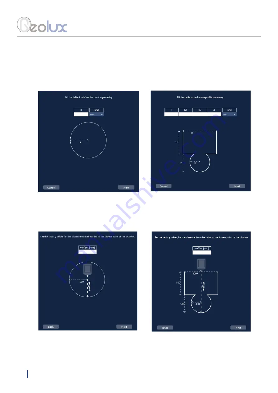
When the user selects a certain shape, a table and a picture of the selected shape appear. The user has
to fill the table and select the desired unit. The required values from the table are shown on the picture
below the table. The following pictures (20. – 25.) show the definition of 2 different channel shapes.
Clicking the
Next
button leads to the next step, i.e. defining the y offset of the radar, Picture 24.
The required y offset distance is clearly show in the picture, as well as the values defined in the previous
step. If changes need to be made to the values from the previous step, it can be done by clicking the
Back
button.
Picture 23. Defining the Channel Geometry of a Predefined Shape
Picture 24. Defining the y Offset of the Radar


