5-130
T35 Transformer Protection System
GE Multilin
5.6 GROUPED ELEMENTS
5 SETTINGS
5
b) PERCENT DIFFERENTIAL
PATH: SETTINGS
GROUPED ELEMENTS
SETTING GROUP 1(6)
TRANSFORMER
PERCENT DIFFERENTIAL
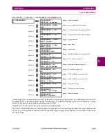
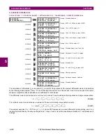
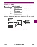
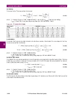
The calculation of differential (
I
d
) and restraint (
I
r
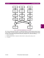
) currents for the purposes of the percent differential element is described
by the following block diagram, where “
Σ
” has as its output the vector sum of inputs, and “max” has as its output the input of
maximum magnitude; these calculations are performed for each phase.
The differential current is calculated as a vector sum of currents from all windings after magnitude and angle compensation.
(EQ 5.26)
The restraint current is calculated as a maximum of the same internally compensated currents.
(EQ 5.27)
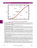
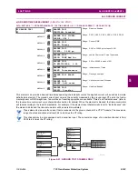
The element operates if
I
d
> PKP and
I
d
/
I
r
>
K
, where PKP represents a percent differential pickup setting and
K
is a
restraint factor defined by the relays settings Slope 1, Slope 2, and a transition area between breakpoint 1 and breakpoint 2
settings.
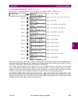
PERCENT
DIFFERENTIAL
PERCENT DIFFERENTIAL
FUNCTION: Disabled
Range: Disabled, Enabled
MESSAGE
PERCENT DIFFERENTIAL
PICKUP: 0.100
pu
Range: 0.050 to 1.000 pu in steps of 0.001
MESSAGE
PERCENT DIFFERENTIAL
SLOPE 1: 25%
Range: 15 to 100% in steps of 1
MESSAGE
PERCENT DIFFERENTIAL
BREAK 1: 2.000 pu
Range: 1.000 to 2.000 pu in steps of 0.001
MESSAGE
PERCENT DIFFERENTIAL
BREAK 2: 8.000 pu
Range: 2.000 to 30.000 pu in steps of 0.001
MESSAGE
PERCENT DIFFERENTIAL
SLOPE 2: 100%
Range: 50 to 100% in steps of 1
MESSAGE
INRUSH INHIBIT
FUNCTION: Adapt. 2nd
Range: Disabled, Adapt. 2nd, Trad. 2nd
MESSAGE
INRUSH INHIBIT
MODE: Per phase
Range: Per phase, 2-out-of-3, Average
MESSAGE
INRUSH INHIBIT
LEVEL: 20.0% fo
Range: 1.0 to 40.0% of f
0
in steps of 0.1
MESSAGE
OVEREXCITN INHIBIT
FUNCTION: Disabled
Range: Disabled, 5th
MESSAGE
OVEREXCITN INHIBIT
LEVEL: 10.0% fo
Range: 1.0 to 40.0% of f
0
in steps of 0.1
MESSAGE
PERCENT DIFF BLOCK:
Off
Range: FlexLogic operand
MESSAGE
PERCENT DIFFERENTIAL
TARGET: Self-reset
Range: Self-reset, Latched, Disabled
MESSAGE
PERCENT DIFFERENTIAL
EVENTS: Disabled
Range: Disabled, Enabled
I
d
I
1
comp
I
2
comp
I
3
comp
I
4
comp
I
5
comp
I
6
comp
+
+
+
+
+
=
I
r
max
I
1
comp
I
2
comp
I
3
comp
I
4
comp
I
5
comp
I
6
comp
,
,
,
,
(
,
)
=
Содержание T35 UR Series
Страница 10: ...x T35 Transformer Protection System GE Multilin TABLE OF CONTENTS ...
Страница 48: ...2 18 T35 Transformer Protection System GE Multilin 2 2 SPECIFICATIONS 2 PRODUCT DESCRIPTION 2 ...
Страница 314: ...5 192 T35 Transformer Protection System GE Multilin 5 10 TESTING 5 SETTINGS 5 ...
Страница 338: ...6 24 T35 Transformer Protection System GE Multilin 6 5 PRODUCT INFORMATION 6 ACTUAL VALUES 6 ...
Страница 350: ...7 12 T35 Transformer Protection System GE Multilin 7 2 TARGETS 7 COMMANDS AND TARGETS 7 ...
Страница 366: ...8 16 T35 Transformer Protection System GE Multilin 8 2 CYBERSENTRY 8 SECURITY 8 ...
Страница 382: ...9 16 T35 Transformer Protection System GE Multilin 9 5 COMMISSIONING TEST TABLES 9 COMMISSIONING 9 ...
Страница 406: ...A 14 T35 Transformer Protection System GE Multilin A 1 PARAMETER LISTS APPENDIX A A ...
Страница 540: ...D 10 T35 Transformer Protection System GE Multilin D 1 IEC 60870 5 104 PROTOCOL APPENDIX D D ...
Страница 552: ...E 12 T35 Transformer Protection System GE Multilin E 2 DNP POINT LISTS APPENDIX E E ...
Страница 560: ...F 8 T35 Transformer Protection System GE Multilin F 3 WARRANTY APPENDIX F F ...


