9-8
T35 Transformer Protection System
GE Multilin
9.2 DIFFERENTIAL CHARACTERISTIC TEST EXAMPLES
9 COMMISSIONING
9
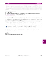
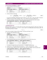
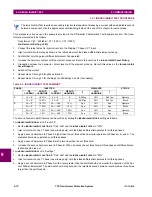
f) SLOPE 2 TEST
Inject currents in such a manner that the magnitude of
I
r
is larger than the restraint current at Breakpoint 2; that is,
(EQ 9.11)
1.
Change the current magnitudes as follows:
2.
The following differential and restraint current should be read from the T35 actual values menu:
Since
and lower than the required 95%, the Percent Differential element will not operate.
3.
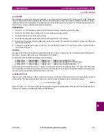
Adjust the
I
1
current as shown below (thereby increasing
I
d
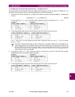
) and verify that the relay operates.
4.
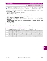
The following differential and restraint current should appear in the T35 actual values menu:
5.
The actual
ratio is now 95.9%. Verify that the element operates correctly.
g) SUMMARY
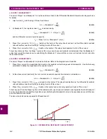
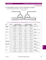
The above tests describe the principles of testing the differential element for all regions from the operating characteristic.
For verification of more points, one should consider adjusting the magnitude of the restraint current
I
r
to the desired portion
of the characteristic and change the other current to vary
I
d
until the relay operates. Use the Excel tool to compare the
actual and expected operating values.
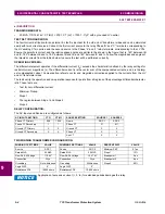
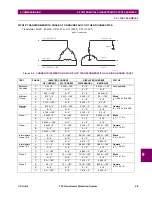
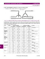
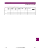
A blank result table is provided at the end of this chapter for convenience.
WINDING 1
WINDING 2
PHASE SINGLE CURRENT (I
1
)
PHASE SINGLE CURRENT (I
2
)
A
0 A
∠
0°
A
0 A
∠
0°
B
0.5 A
∠
0°
B
9 A
∠
–180°
C
0.5 A
∠
–180°
C
9 A
∠
0°
PHASE DIFFERENTIAL CURRENT (I
d
)
PHASE RESTRAINT CURRENT (I
r
)
A
0
∠
0°
A
0
∠
0°
B
8.078 pu
∠
–180°
B
9 pu
∠
–180°
C
8.078 pu
∠
0°
C
9 pu
∠
0°
WINDING 1
WINDING 2
PHASE SINGLE CURRENT (I
1
)
PHASE SINGLE CURRENT (I
2
)
A
0 A
∠
0°
A
0 A
∠
0°
B
0.2 A
∠
0°
B
9 A
∠
–180°
C
0.2 A
∠
–180°
C
9 A
∠
0°
PHASE DIFFERENTIAL CURRENT (I
d
)
PHASE RESTRAINT CURRENT (I
r
)
A
0
∠
0°
A
0
∠
0°
B
8.631 pu
∠
–180°
B
9 pu
∠
–180°
C
8.631 pu
∠
0°
C
9 pu
∠
0°
I
r
I
r
Break 2
(
)
>
8 pu
=
I
d
I
r
⁄
89.8%
=
I
d
I
r
⁄
Содержание T35 UR Series
Страница 10: ...x T35 Transformer Protection System GE Multilin TABLE OF CONTENTS ...
Страница 48: ...2 18 T35 Transformer Protection System GE Multilin 2 2 SPECIFICATIONS 2 PRODUCT DESCRIPTION 2 ...
Страница 314: ...5 192 T35 Transformer Protection System GE Multilin 5 10 TESTING 5 SETTINGS 5 ...
Страница 338: ...6 24 T35 Transformer Protection System GE Multilin 6 5 PRODUCT INFORMATION 6 ACTUAL VALUES 6 ...
Страница 350: ...7 12 T35 Transformer Protection System GE Multilin 7 2 TARGETS 7 COMMANDS AND TARGETS 7 ...
Страница 366: ...8 16 T35 Transformer Protection System GE Multilin 8 2 CYBERSENTRY 8 SECURITY 8 ...
Страница 382: ...9 16 T35 Transformer Protection System GE Multilin 9 5 COMMISSIONING TEST TABLES 9 COMMISSIONING 9 ...
Страница 406: ...A 14 T35 Transformer Protection System GE Multilin A 1 PARAMETER LISTS APPENDIX A A ...
Страница 540: ...D 10 T35 Transformer Protection System GE Multilin D 1 IEC 60870 5 104 PROTOCOL APPENDIX D D ...
Страница 552: ...E 12 T35 Transformer Protection System GE Multilin E 2 DNP POINT LISTS APPENDIX E E ...
Страница 560: ...F 8 T35 Transformer Protection System GE Multilin F 3 WARRANTY APPENDIX F F ...

