


5-178
M60 Motor Protection System
GE Multilin
5.6 GROUPED ELEMENTS
5 SETTINGS
5
c) UNDERPOWER
PATH: SETTINGS
GROUPED ELEMENTS
SETTING GROUP 1(6)
POWER
UNDERPOWER
UNDERPOWER 1
Two underpower elements are provided.
The underpower function uses the source selected by the
SYSTEM SETUP
MOTOR
MOTOR LINE SOURCE
setting.
Phase currents and voltages must configured on that source, otherwise the underpower function will not be functional. The
underpower element responds to total three-phase apparent power measured from the phase current and voltages.
When the underpower element is enabled, a trip or alarm are initiated once the magnitude of three-phase apparent power
falls below the pickup level for a period of time specified by the delay. For example, underpower may be used to detect
loss-of-load conditions. Loss of load conditions will not always cause a significant loss of current. Power is a more accurate
representation of loading and may be used for more sensitive detection of load loss or pump cavitations. This may be espe-
cially useful for detecting process related problems.
•
UNDERPOWER 1 START BLOCK DELAY
: This setting specifies the length of time to block the underpower function
when motor is starting. If not in the starting state, the motor status is indicated by the
MOTOR OFFLINE
operand. Refer
to the
Motor setup
section for additional information on using the
MOTOR OFFLINE
operand for state determination.
The underpower element is active only when the motor is running and is blocked upon the initiation of a motor start for
a period of time specified by this setting. For example, this block may be used to allow pumps to build up head before
the underpower element trips or alarms. A value of 0 specifies that the feature is not blocked from start. For values
other than 0, the feature is disabled when the motor is stopped and also from the time a start is detected until the time
entered expires.
•
UNDERPOWER 1 ALARM PWR PICKUP
: This setting specifies a pickup threshold for the alarm stage. The base per-
unit power quantity is 3 × VT pu base × CT pu base per source selected as a motor line source. The alarm pickup
threshold should be less than the motor load current during normal operations.
•
UNDERPOWER 1 ALARM PICKUP DLY
: This setting specifies a time delay for the alarm stage. The time delay
should long enough to overcome any short lowering of the current (for example, during system faults).
•
UNDERPOWER 1 TRIP PWR PICKUP
: This setting specifies a pickup threshold for the trip stage. The base quantity
is 3-phase power on primary side, which should be calculated as
√
3 x Phase CT Primary x Phase VT Ratio x Phase
VT Secondary in case of delta connected VTs; and 3 x Phase CT Primary x Phase VT Ratio x Phase VT Secondary in
case of wye connected VTs. This setting should be less than the corresponding setting for the alarm stage.
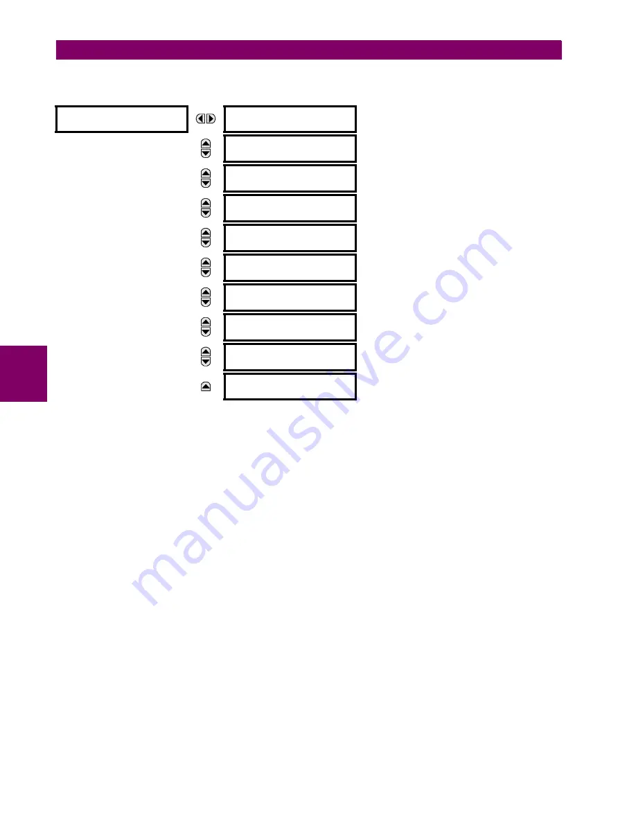
UNDERPOWER
UNDERPOWER 1
FUNCTION: Disabled
Range: Enabled, Disabled
MESSAGE
UNDERPOWER 1 START
BLOCK DLY:
0.50 s
Range: 0.00 to 600.00 s in steps of 0.01
MESSAGE
UNDERPOWER 1 ALARM
PWR PICKUP: 0.50 pu
Range: 0.05 to 2.00 pu in steps of 0.01
MESSAGE
UNDERPOWER 1 ALARM
PICKUP DLY:
2.00 s
Range: 0.00 to 600.00 s in steps of 0.01
MESSAGE
UNDERPOWER 1 TRIP
PWR PICKUP: 0.50 pu
Range: 0.05 to 2.00 pu in steps of 0.01
MESSAGE
UNDERPOWER 1 TRIP
PICKUP DLY:
1.00 s
Range: 0.00 to 600.00 s in steps of 0.01
MESSAGE
UNDERPOWER 1 TRIP
RESET DLY:
1.00 s
Range: 0.00 to 600.00 s in steps of 0.01
MESSAGE
UNDERPOWER 1 BLOCK:
Off
Range: FlexLogic operand
MESSAGE
UNDERPOWER 1 TARGET:
Self-reset
Range: Self-reset, Latched, Disabled
MESSAGE
UNDERPOWER 1 EVENTS:
Disabled
Range: Enabled, Disabled
Содержание M60 UR Series
Страница 10: ...x M60 Motor Protection System GE Multilin TABLE OF CONTENTS ...
Страница 98: ...3 40 M60 Motor Protection System GE Multilin 3 3 DIRECT INPUT OUTPUT COMMUNICATIONS 3 HARDWARE 3 ...
Страница 128: ...4 30 M60 Motor Protection System GE Multilin 4 3 FACEPLATE INTERFACE 4 HUMAN INTERFACES 4 ...
Страница 238: ...5 110 M60 Motor Protection System GE Multilin 5 4 SYSTEM SETUP 5 SETTINGS 5 Figure 5 29 DISCONNECT SWITCH SCHEME LOGIC ...
Страница 410: ...5 282 M60 Motor Protection System GE Multilin 5 10 TESTING 5 SETTINGS 5 ...
Страница 413: ...GE Multilin M60 Motor Protection System 6 3 6 ACTUAL VALUES 6 1 OVERVIEW 6 FIRMWARE REVISIONS See page 6 29 ...
Страница 440: ...6 30 M60 Motor Protection System GE Multilin 6 5 PRODUCT INFORMATION 6 ACTUAL VALUES 6 ...
Страница 452: ...7 12 M60 Motor Protection System GE Multilin 7 2 TARGETS 7 COMMANDS AND TARGETS 7 ...
Страница 462: ...9 8 M60 Motor Protection System GE Multilin 9 2 BATTERIES 9 MAINTENANCE 9 ...
Страница 474: ...A 12 M60 Motor Protection System GE Multilin A 1 PARAMETER LISTS APPENDIX A A ...
Страница 584: ...B 110 M60 Motor Protection System GE Multilin B 4 MEMORY MAPPING APPENDIX B B ...
Страница 614: ...C 30 M60 Motor Protection System GE Multilin C 7 LOGICAL NODES APPENDIX C C ...
Страница 630: ...E 10 M60 Motor Protection System GE Multilin E 1 IEC 60870 5 104 PROTOCOL APPENDIX E E ...
Страница 642: ...F 12 M60 Motor Protection System GE Multilin F 2 DNP POINT LISTS APPENDIX F F ...
Страница 644: ...G 2 M60 Motor Protection System GE Multilin G 1 RADIUS SERVER CONFIGURATION APPENDIX G G ...
Страница 652: ...H 8 M60 Motor Protection System GE Multilin H 3 WARRANTY APPENDIX H H ...
Страница 662: ...x M60 Motor Protection System GE Multilin INDEX ...


