4. PROGRAMMING THE UNIT
GEK-106305A
DTR Digital Tap Changer Controller
47
The help text shown at the bottom displays the possible actions that can be taken in that screen:
Arrows are used from moving from one alarm to another
By pressing F1, we move to the MEASURES screen
By pressing F2, we acknowledge the selected alarm (when we are placed on an alarm, its colour is shown in
negative).
By pressing F3, we automatically acknowledge all the alarms appearing on the alarms screen.
4.7 MEASURES SCREEN
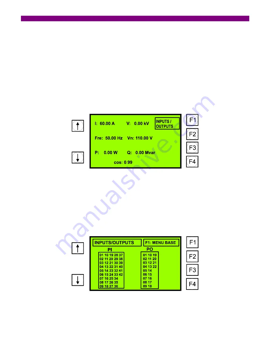
If we move from the alarms screen to the measures screen, the display will look as below:
The displayed values are values on the primary side.
4.8 INPUTS/OUTPUTS SCREEN
From the measures screen, we can move to the inputs/outputs screen by pressing the F1 key. The displayed screen
will look as follows:
Those inputs/outputs active at a given moment, will be displayed with a dark shadow.
Содержание DTR GEK-106305A
Страница 5: ...TABLE OF CONTENTS 4 DTR Digital Tap Changer Controller GE 106305A ...
Страница 49: ...4 PROGRAMMING THE UNIT 48 DTR Digital Tap Changer Controller GE 106305A ...
Страница 55: ...5 TECHNICAL CHARACTERISTICS 54 DTR Digital Tap Changer Controller GE 106305A ...
Страница 71: ...8 INSTALLATION AND MAINTENANCE 70 DTR Digital Tap Changer Controller GE 106305A ...
Страница 83: ...9 KEYPAD AND DISPLAY 82 DTR Digital Tap Changer Controller GE 106305A ...
Страница 87: ...FIGURES 86 DTR Digital Tap Changer Controller GE 106305A FIGURE 3 PANEL MOUNTING DIAGRAM ...
Страница 88: ...FIGURES GEK 106305A DTR Digital Tap Changer Controller 87 FIGURE 4 RS 232 CONNECTION ...
Страница 89: ...FIGURES 88 DTR Digital Tap Changer Controller GE 106305A FIGURE 5 DIMENSIONS DIAGRAM ...
Страница 90: ...FIGURES GEK 106305A DTR Digital Tap Changer Controller 89 FIGURE 6 FRONT VIEW ...
Страница 91: ...FIGURES 90 DTR Digital Tap Changer Controller GE 106305A FIGURE 8 GENERIC REAR VIEW ...


