background image

26

I N S TA L L AT I O N ,  O P ER AT I O N S  A N D  M A I N T EN A N C E  M A N UA L

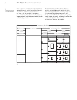
1. Internal equipment control wiring
2. Terminal boards
3. Space for purchaser's field control wiring


39


39
Control wiring 
termination trough

1

2

3

Ground bus

All ReliaGear LV SG sections are grounded to the 
internal equipment ground bus, Figure 40, located 
at the bottom or the top of the cable compartment.


40
Cable termination 
compartment

1. Feeder run backs
2. Vertical riser bus covers
3. Horizontal main bus
4. Ground bus (behind steel cover)


40

4

1

3

2

A neutral bus, insulated from ground, is provided in 
the bus area on switchgear designed for four-wire 
systems. The neutral bus is located either near the 
top or near the bottom of the cable compartment. 
It includes provisions for terminating the neutral 
conductor of four-wire feeder cables and also 
direct mounting of the neutral sensor as required 
for those feeder system circuit breakers having a 
ground fault trip function.

Содержание ABB ReliaGear LV SG

Страница 1: ...INSTALLATION OPER ATIONS AND MAINTENANCE MANUAL ReliaGear LV SG Low voltage switchgear ...

Страница 2: ...r to provide for every possible contingency to be met in connection with installation operation or maintenance Should further information be desired or should particular problems arise which are not covered sufficiently for the Purchaser s purposes the matter should be referred to your ABB sales representative These instructions are intended for use by qualified personnel only ...

Страница 3: ... Receiving handling and storage 14 27 Switchgear description 28 43 Equipment installation 44 47 Installing and removing circuit 48 49 Testing and inspection 51 53 Cooling fan control module 54 58 Operating the switchgear 59 Energizing the switchgear 60 64 Maintaining the switchgear 65 74 Appendices ...

Страница 4: ...rranty This document is based on information available at the time of publication While efforts have been made to ensure accuracy the information contained herein does not cover all details or variations in hardware and software nor does it provide for every possible contingency in connection with installation operation and maintenance Features may be described herein that are not present in all h...

Страница 5: ...n the accompanying drawings please contact your ABB sales representative Introduction Instruction book arrangement Information and procedures in this instruction book are divided as follows Introduction gives a brief account of the equipment s function and provides for general information and applicable data for the equipment and its components Receiving handling and storage describes procedures r...

Страница 6: ...ue values circuit breaker rejection features circuit breaker information and spare parts Related publications Addenda to this instruction book are the available service and maintenance publications supplied separately for circuit breakers relays and other devices not described in this instruction book 01 ReliaGear LV SG low voltage switchgear In addition to instruction books the following As built...

Страница 7: ...ber in which they are stored Large items such as breaker lifting devices and dollies used with indoor equipment will always be shipped in separate crates or cartons See Figure 03 Inspecting for damage All equipment leaving the factory is carefully inspected and packed by personnel experienced in the proper handling and packing of electrical equipment Upon receipt of any equipment immediately perfo...

Страница 8: ...7 RELIAGEAR LV SG LOW VOLTAGE SWITCHGE AR Spare compartment Carton containing loose material Shipping label 1 2 3 02 Packaging of loose material for shipment 03 Carton containing breaker lifting device ...

Страница 9: ...bles and an overhead crane each with a minimum load rating of twice the weight of the switchgear Estimated weights for shipping splits appear on the Front View drawings Example Switchgear section weight 5 000 pounds The crane and the four lift cables must have a minimum load lifting capacity of 10 000 pounds Warning The angle between the cables and the top of the equipment must be at least 45 degr...

Страница 10: ...tions side support timbers must be placed along the sides to prevent any damage that could be caused by the lifting cables In addition spreader bars must be inserted between each lift cable both front and rear Spreader bar locations must be on the sides and above the switchgear equipment as shown in Fig 06 Proceed to lift and place the outdoor switchgear utilizing all the precautions and requireme...

Страница 11: ...ear of the equipment 3 Raise equipment and position one roller under the skids close to the raised end of the line up 4 Carefully lower the gear until it rests on the roller as shown in Figure 10 5 Repeat the lifting process at the other end and place the appropriate number of rollers under the skids spacing them evenly across the width of the line up Spreaders and timber not furnished with equipm...

Страница 12: ...e switchgear to its final site position the rollers that are freed from the rear of the switchgear are then repositioned at the forward end This procedure should be continued until the switchgear is in its final location Figure 11 8 When the switchgear is in its final position remove all lug bolts holding the shipping skids to the switchgear line up 9 Insert the tines of the forklift at one end of...

Страница 13: ...the appropriate number of rollers under the skids spacing them evenly across the width of the line up Gently lower the gear onto the rollers 13 Recommended method of jacking outdoor enclosure Partial front or rear view of jacking Partial side view of jacking Front view Jacking timber not furnished with switchgear Cable Rear or front Jack here 3 While carefully pushing the switchgear to its final s...

Страница 14: ...accomplished by making a temporary power supply connection to the heaters already installed in the equipment Caution If the space heaters are to be temporarily energized from external source it is important to remove the fuses on the secondary side of the control power transformer This precaution is to prevent a feedback of higher voltage to other portions of the equipment through the CPT primary ...

Страница 15: ...it protective devices controls and instrumentation It may also be an integral part of a load center unit substation either single ended or double ended Switchgear description Intersectional control wiring trough Breaker or instrument compartment A B C D Breaker compartment Breaker compartment Breaker compartment Neutral bus Vertical riser bus bars Cable termination area Breaker compartment run bac...

Страница 16: ...ligning primary and secondary disconnecting contacts breaker locking mechanism and integral trip unit The individual sections compartments and devices are described in the following paragraphs Figure 15 is an outline of a typical single ended load center unit substation illustrating the nomenclature used for all equipment A A A B B B C C D D D A B Primary section Transformer ReliaGear LV SG sectio...

Страница 17: ... fuses pilot lights and a RELT switch Fuses for the charge close and trip circuits of the electrically operated SACE Emax 2 breakers are mounted on the panel Routine wiring inspections and fuse checks or fuse replacements can be performed with the breaker compartment door in the closed position so that operators are protected from the energized primary circuits 1 Control circuit fuses 2 Pilot ligh...

Страница 18: ...nded steel barriers on the top sides bottom and front In the back a flame retardant track resistant glass filled polyester base minimizes the possibility of fault communication between compartments or to the bus 1 Breaker position indicator 2 Push to operate racking mechanism button shown engaged 3 Racking handle 4 Racking handle storage 1 Secondary disconnects 2 Position switch location not shown...

Страница 19: ... when the circuit breaker is closed and in the CONNECTED position Although the breaker compartment door may be opened in any position it is recommended that the door only be opened when the breaker is in the DISCONNECTED or WITHDRAWN position The dedicated front mounted auxiliary ventilated compartment is constructed with grounded metal barriers on all sides resulting in a segregated compartment t...

Страница 20: ...ition As the circuit breaker is racked from the DISCONNECT Position to the TEST Position the shutters remain fully closed As the breaker is racked from the TEST Position to the CONNECT Position the shutters open allowing the breaker to connect to the primary disconnects Figure 24 shows the shutter assembly with the shutter in the open position Danger Hazard of electrical shock or burn Turn off pow...

Страница 21: ...r high stacking 22 inch wide sections E4 2 Emax 2 circuit breaker 2 000 ampere frame size Up to 100kAIC interrupting rating Four high stacking 22 inch wide sections E4 2 Emax 2 circuit breaker 3 200 ampere frame size Up to 100kAIC interrupting rating Available in 22 inch wide sections E6 2 Emax 2 circuit breaker 5 000 ampere frame size Up to 100kAIC interrupting rating Available in 38 inch wide se...

Страница 22: ...de as required to accommodate the space requirements The compartment doors on the front of the sections are hinged and latched in the same manner as breaker compartment doors Generally transition sections will be 22 inches wide for close coupling to transformers and match and line up to non ABB equipment Power company metering requirements generally require either a 38 inch or 49 inch wide auxilia...

Страница 23: ...eaker compartment The horizontal bus bars are supported by the power connectors which are bolted to the vertical bus bars All bolted supports and connections are accessible from the rear for maintenance The bus area is fully isolated from the breaker instrument and auxiliary compartments by the molded bases or glass polyester sheet 1 Enclosed fuse block 2 Open fuse block 1 Vertical riser bus 2 Run...

Страница 24: ...rmer if the switchgear were part of a Load Center Unit Substation If because of shipping and or handling considerations the equipment cannot be handled in one piece it can be split into two or more shipping sections at the factory The individual shipping splits require both mechanical and electrical connections between sections to be made in the field At these shipping splits provisions are made f...

Страница 25: ... busway or existing equipment Insulation and isolation of the vertical riser bus bars Figure 36 is provided by installing phase isolation barriers not shown between the bus bars and by the vertical bus barrier which covers over the bus bars The phase isolation barriers and riser bus covers are constructed from insulating material Insulation of the horizontal main bus bars is achieved by an oven cu...

Страница 26: ...ompartment Figure 38 provides for cable installation and terminations The cable bending space meets the requirements of the National Electric Code Various arrangements of single or double cable terminals are provided depending upon the purchaser s requirements When specified racks for the support of feeder cables are located in the cable compartment The actual support of the cables is provided by ...

Страница 27: ...le termination compartment 1 Feeder run backs 2 Vertical riser bus covers 3 Horizontal main bus 4 Ground bus behind steel cover 40 4 1 3 2 A neutral bus insulated from ground is provided in the bus area on switchgear designed for four wire systems The neutral bus is located either near the top or near the bottom of the cable compartment It includes provisions for terminating the neutral conductor ...

Страница 28: ...lifting device A portable breaker lifting device available as an optional accessory is used for lifting the Emax 2 breakers 42 Location of space heater indoor enclosure 1 2 Outdoor switchgear Switchgear designed for outdoor installations is fully weatherproofed See Figure 41 A weatherproof housing completely encloses the switchgear and may be provided with a walk in front aisle for easy access to ...

Страница 29: ...nce In locating the switchgear adequate aisle space must be provided at the front and rear of the equipment to ensure proper ventilation of the equipment and to allow service and maintenance of the equipment with the front and rear doors open The recommended aisle space is shown on the floor plan supplied with the equipment drawings The switchgear equipment should be placed in an area where clean ...

Страница 30: ...witchgear structure to assure proper mechanical and electrical connections between shipping splits and to assure proper interfacing to other close coupled equipment 44 Indoor enclosure anchor locations 44 Embedded C Channel if used ABB switchgear and load center substations are frequently mounted on steel floors and or structural steel in industrial installations such as a mezzanine to minimize us...

Страница 31: ...hough the equipment can be mounted directly on a smooth level surface it is recommended that recessed steel channels be installed to support the switchgear The floor channel sills under the front center and rear of the switchgear base should be embedded in a level concrete slab with their top surfaces flush with the finished floor Notice Four 4 clamp plates see Figure 47 are required for each outd...

Страница 32: ...ing recommendations for equipment subject to operational and or environmental seismic shock loading Anchor bolts and channels are to be provided by the purchaser the clamp plates Figure 45 are not supplied with the equipment It is recommended that the anchor bolts be 5 8 inch diameter 47 Outdoor enclosure clamp plate 47 Dimension in inches 46 DANGER WARNING CAUTION NOTICE ...

Страница 33: ...prevent damage and possible misoperation of the switchgear equipment Detailed assembly and installation instructions indoor equipment The recommended procedure for installation of an indoor switchgear or load center unit substation is as follows 1 Position the equipment Position the equipment or sections of the complete equipment in their final location 1 Indoor Lifting Plates 48 48 Lifitng plate ...

Страница 34: ...n to the control and metering circuits Warning All switchgear equipment must be adequately grounded for safety Failure to ground equipment properly may result in serious injury Figure 52 illustrates the general location of the buses that must be spliced across the shipping splits 50 Location of through bolts dimension in inches 2 Remove the shipping skids The equipment is fastened to the shipping ...

Страница 35: ...hat the ground bus be connected first since it provides an integral ground for all the equipment It must also be connected to the station ground prior to proceeding with the installation A 4 0 AWG cable connector is located in the bottom of the transition section or in the incoming line compartment if a transition section is not included for terminating the purchaser s cable connection to ground T...

Страница 36: ...n one bar is used per phase normally the 2000 A and larger main bus ratings After assembly of the splice bars and spacers the 1 2 13 bolts should be tightened to a torque of 35 40 ft lbs After completing the installation of the main bus splice bars the joint covers may be mounted and secured by a 3 8 16 nylon bolt and polyester flat washer if the bus insulation option has been supplied with the eq...

Страница 37: ...mbly 2 Apply gasket material After removal of the lifting plates see Figure 59 it is necessary to apply the presstite gasket material Figures 59 and 60 to the mounting surface of the roof flange The gasket material is supplied with the equipment 3 Align sections Align the two sections with the mating surfaces butted together 4 Fasten sections together Referring to Figure 50 the mating sections of ...

Страница 38: ...for themain horizontal neutral and ground buses should be done in accordance with the instructions for indoor equipment as described earlier in this instruction book 60 Cross section view of assembled roof joint 61 Door seals 60 61 10 Connect the transformer secondary The installation of the transformer connection straps to the incoming bus should be done in accordance with the instructions for in...

Страница 39: ...o the channel sill is the use of two linear fillet welds for each section It is recommended that each weld be 2 1 2 inches long min with a 3 16 inch fillet min A third method for anchoring the rear of the equipment is to remove the rear sill angle from the switchgear and weld the rear bottom width post to the channel sill These welds should like the front welds have a 3 16 inch min fillet and each...

Страница 40: ...ar equipment Notice To maintain the minimum contact resistance across bolted bus joints it is recommended that the joint contact surfaces be coated with a film of lubricating grease A can of this grease is supplied with the equipment Do not put grease on the bolt threads as this will affect the clamping force exerted by the bolt Control wire connections For external control wiring refer to Figure ...

Страница 41: ... cable terminals in the addendum of this manual See Appendix A Table A 2 For aluminum cables wire brush the wire strands thoroughly Immediately after wire brushing coat the cable strands with a quality oxide inhibiting compound such as Penetrox A Insert exposed wires into the terminals and tighten the set screws in accordance with values shown in the torque Table A 2 in Appendix A of this Instruct...

Страница 42: ...eter continuous nylon rope or equivalent minimum 2000 pounds tensile strength at 6 inches from the main cable terminals make five revolutions around the A and B phase main cables making sure the rope does not overlap Make five revolutions around the B and C phase main cables With the remaining rope wrap around the main cable lashing between the B and C phase and the cable brace if present with a m...

Страница 43: ... the equipment Notice Maximum lifting capacity is 700 lbs equipment Figure 70 The rear wheels can then be hooked under the channel and the front wheels can be positioned on the front track See Figure 71 The runner guide at the rear should then be reassembled Figure 72 Stop blocks are provided at each end of the front track to prevent the breaker lifting device from rolling off the ends of the trac...

Страница 44: ...ver both sections of the shipping split and align the four mounting holes Install the four screws that were previously removed 1 After the splice plates have been installed run the breaker lifting device over the assembled shipping split to check the alignment of the rail and runner If necessary adjust the rail and or runner for smooth operation of the rollers on the breaker lifting device On seis...

Страница 45: ... identification card on the breaker shipping carton The breaker may also be identified using the 20 digit catalog number 3 To locate the breaker in the proper compartment refer to the breaker location list on the front view drawing Find the proper breaker by the identification card on the breaker carton All identical breakers will have the same mark and catalog number Installing and removing circu...

Страница 46: ...ify that the breaker is the correct type for that compartment 3 Ensure that the breaker is OPEN 4 Apply a thin fresh coat of lubricating grease to the breaker s primary disconnects 5 Ensure that the position indicator on the circuit breaker is in in the DISCONNECTED position and is correctly positioned for initial engagement To do this open the racking handle door and insert the racking handle and...

Страница 47: ...racking mechanism button 2 Breaker position indicator 3 Racking handle 8 Move the breaker into the compartment to the DISCONNECT position If an incorrect breaker has been installed the interference pins on the breaker will interfere with the rejection pins in the compartment prior to reaching the disconnect position 9 Slide rails back into compartment Close the compartment door and rotate latch tu...

Страница 48: ...med with the door closed If the breaker closing spring is fully charged press the Discharge button to discharge the energy 3 Open the compartment door and fully extend the draw out rails Move the breaker out until the rail stops This is the WITHDRAWN position The Emax 2 circuit breaker has an interlock which prevents the breaker from being able to move to the DISCONNECT position if the breaker s m...

Страница 49: ...he trip setting adjustments of the trip unit for each circuit breaker may be at any setting when shipped from the factory and must be correctly set prior to energization of the equipment General instructions for setting the relays are given in the applicable Relay or Trip Unit Instruction Book The extent of the tests on the equipment as a whole will depend on the type and function of the equipment...

Страница 50: ...raw out construction it is automatically connected to the trip unit in the breaker via a draw out secondary disconnect terminal Caution Never disengage the trip unit on a breaker that is energized and carrying load current This will open circuit the current sensors allowing dangerous and damaging voltages to develop Complete Instructions for testing the trip units are included with the test set Th...

Страница 51: ...on Zone selective interlocking ZSI ZSI be used to minimize circuit breaker trip times closer to the fault The protection is provided by connecting all the zone selectivity outputs of the trip units belonging to the same zone and taking this signal to the trip unit input that is immediately upstream Each circuit breaker that detects a fault reports it to the circuit breaker upstream the circuit bre...

Страница 52: ...is 0 7 amps 24Vdc 5 fans installed Remote monitoring of the fan control circuit is optionally available Notice Variations of the fan control circuit may be provided Operators should review and understand the As built documents provided with the equipment from the factory to confirm final fan control circuitry Table 8 provides the current threshold values that EKIP Touch or Hi Touch trip unit s Ala...

Страница 53: ... control instrument tray panel 86 ReliaGear Low voltage Switchgear cooling fan control circuit 1 Fan control power fuse 2 Current under set value indicating light 3 Fan relay On indicating light 4 Fan on indicating light s 5 Illuminating fan control switch 1 2 3 5 4 ...

Страница 54: ... held in the TEST position an operator can perform a functional test on the fan cooling system without having to exceed the values shown in Table 8 While the Illuminated Fan Control Switch is held in the TEST position the following events will indicate a heathy fan cooling system Amber current under set value indicating light is not illuminated Red fan relay on indicating light is illuminated Each...

Страница 55: ...t breakers closing operation Electrically operated breakers may be closed by ac control power or dc normally station or standby battery control power Refer to the provided elementary diagrams for information on control circuitry Operating the switchgear Opening operation A shunt trip device is used for electrical tripping and each breaker can have up to two shunt trip accessories installed Circuit...

Страница 56: ...he cradle The racking mechanism is driven by a removable racking handle or remote racking device see 1SXU200040C0201 for RDD ordering details which engages the mechanism The handle is inserted through an opening in the cradle escutcheon Turning the handle in a clockwise direction drives the breaker into the compartment As the breaker disconnect fingers engage the stab tips a high force will be fel...

Страница 57: ...ng the top hinge pin plate and allow the pin to drop out of the hinge block See Figure 91 3 Move the top of the door away from the switchgear avoiding the door stop and lift the door out of the lower hinge pin socket Retain the washers Door installation To install the switchgear door proceed as follows 1 Insert washer then place lower hinge pin into hinge pin socket on switchgear See Figure 88 2 S...

Страница 58: ...erlock interaction Said breaker will require modification see instruction manual 1SDH001000R0748 Key interlock operation check The operation of the key interlock should be checked as follows 1 With the breaker in the CONNECT position manually trip the breaker This then allows the key interlock to activate a trip free status of the breaker While the breaker is in the trip free state the key can be ...

Страница 59: ... shutter on each cubicle can be padlocked to prevent access to the live primary conductors The breaker must be removed from the compartment to padlock the shutter For E2 2 and E4 2 cradles a minimum of 2 padlocks are required one for the top shutter assembly and one for the bottom shutter assembly For E6 2 a minimum of 4 padlocks are required 2 for the 2 top shutter assemblies and 2 for the 2 bott...

Страница 60: ...cation of Emax 2 protections tested Energizing procedures Caution Energizing switchgear for the first time is potentially dangerous Therefore qualified electrical personnel should be present when the equipment is energized If problems caused by damage or poor installation practices have not been detected in the checkout procedure described previously serious damage can result when power is turned ...

Страница 61: ... energizing the switchgear perform all inspections defined in this document Maintaining the switchgear Maintenance requirements General A periodic maintenance schedule must be established to obtain the best service from the switchgear An annual check of the switchgear devices and all connections should be made as a minimum requirement Equipment subject to highly repetitive operation may require mo...

Страница 62: ...tion as follows 1 Operate each breaker while in the TEST position and check all functions This is particularly important for breakers that normally remain in either the opened or closed positions for long periods of time Warning Primary equipment must be completely de energized while tests on control circuits etc are being conducted Be sure that all areas of feedback from secondary circuits as wel...

Страница 63: ...tion of these devices regularly Refer to Relay Instruction Books for detailed instructions Breaker compartment interiors Warning De energize equipment completely before doing maintenance work in compartments This includes de energizing any connections to outside primary or secondary sources such as transformers tie lines etc Thoroughly clean the interior of the breaker and instrument compartments ...

Страница 64: ...ld include the ambient temperature and humidity Cable and busway compartment Inspect and check the cable and busway compartment as follows 1 Inspect all power cable connections for signs of overheatingand tighten all connections If severe discoloration or if damage is apparent remove the damaged portion of the cable Caution Be sure the condition which caused the over heating has been corrected bef...

Страница 65: ... topcoat should be 24 32 seconds with a 2 Zahn cup The curing schedule for PPG W42713 is dust free in 5 minutes touch in 30 minutes handle in 60 minutes full cure in 7 days Both the primer Sherwin Williams E61 A 60 and paint PPG W42713 should be applied only when temperature is above 55 degrees Fahrenheit Application of special paint will be per the manufacturer s Product Data Sheet which includes...

Страница 66: ...600 700 750 300 800 900 1 000 400 1 250 1 500 1 750 2 000 500 Table A 1 Torque values for low voltage equipment electrical joint hardware other than cable terminals copper tin or silver plated Table A 2 Torque values for cable terminals 1 These torque values are for non lubricated threads 2 Standard nut with conical spring washer or lock washer 1 These torque values are for non lubricated threads ...

Страница 67: ... to each breaker and its cradle The rejection is accomplished by pins on the sides of the breaker and on the sides of the cradle Rejection feature This factory installed pin and gate device prevents the insertion of a circuit breaker into a cradle if the nominal rating of the breaker is incompatible with that of the cassette and its ancillary equipment The information in the following appendices l...

Страница 68: ...67 RELIAGEAR LV SG LOW VOLTAGE SWITCHGE AR E1 2 UL 1066 800A B A 1200A B A 800A N A 1200A N A 800A S A 250A S A 1200A S A 6 7 6 7 6 7 6 7 6 7 6 7 6 7 ...

Страница 69: ...68 INSTALL ATION OPER ATIONS AND MAINTENANCE MANUAL 800A S A 2000A S A 1200A H A 1600A H A 2000A H A 800A V A 1200A V A 1600A V A 2000A V A 800A H A 1200A S A 1600A S A E2 2 UL 1066 ...

Страница 70: ...69 RELIAGEAR LV SG LOW VOLTAGE SWITCHGE AR E4 2 UL1066 3200A H A 3200A S A 800A V A 800A 125KA 1600A 125KA 3200A 125KA 1600A 125KA 1600A V A 2000A V A 3200A V A ...

Страница 71: ...000A H A 2 3 2 3 3200A V A 2 3 2 3 4000A V A 2 3 2 3 5000A V A 2 3 2 3 6000A V A 2 3 2 3 3200A 150KA 2 3 2 3 4000A 150KA 2 3 2 3 5000A 150KA 2 3 2 3 6000A 150KA 2 3 2 3 3200A 200KA 2 3 2 3 4000A 200KA 2 3 2 3 5000A 200KA 2 3 2 3 6000A 200KA 2 3 2 3 E1 2 Non automatic 800A B A 1200A B A 800A N A 1200A N A 6 7 6 7 6 7 6 7 ...

Страница 72: ...71 RELIAGEAR LV SG LOW VOLTAGE SWITCHGE AR 2000A N A 2 3 2 3 800A S A 2 3 2 3 800A V A 2 3 2 3 1600A S A 2 3 2 3 2000A S A 2 3 2 3 1600A V A 2 3 2 3 2000A V A 2 3 2 3 E2 2 Non automatic ...

Страница 73: ...N OPER ATIONS AND MAINTENANCE MANUAL 3200A S A 2 3 2 3 800A V A 2 3 2 3 1600A V A 2 3 2 3 2000A V A 2 3 2 3 3200A H A 2 3 2 3 3200A V A 2 3 2 3 E4 2 Non automatic E6 2 Non automatic 4000A L A 2 3 2 3 5000A L A 2 3 2 3 ...

Страница 74: ...on including ratings weights accessories etc reference 1SXU200040C0201 SACE Emax 2 UL Catalog 1SDH001330R1002 Operating instructions for the design enginer 1SDH001000R0002 Installation operation maintenance instruction Go to library abb com In the search field type the document number to find the necessary document ...

Страница 75: ...oval 1VAL106903 TG inclusive of cradle stab tip and compartment current transformer instructions 5000A Fan Installation Trip Unit Programming 1VAL106902 TG Go to library abb com In the search field type the document number to find the necessary document Description Order code Lifting Beam E2 2 E4 2 3 Pole RSGLB22423P Lifting Beam E6 2 3 Pole RSGLB623P Overhead Circuit Breaker Lifting Device Crank ...

Страница 76: ...up to date and correct it makes no representations or warranties of any kind express or implied about the completeness accuracy reliability suitability or availability with respect to the information products services or related graphics contained in the document for any purpose Any reliance placed on such information is therefore strictly at your own risk ABB reserves the right to discontinue any...

Отзывы: