48
I N S TA L L AT I O N , O P ER AT I O N S A N D M A I N T EN A N C E M A N UA L
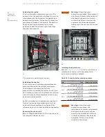
Testing and inspecting
General
After the equipment has been installed and all
connections made, it must be tested and inspected
before it is put in service. Although the equipment
and devices have been tested at the factory, a final
field test must be made to be sure that the
equipment has been properly installed and
that all connections are correct.
Warning:
The equipment must be completely
de-energized while the tests are in progress.
Directions for testing relays, instruments,
and meters are given in the instruction book
furnished for each device. The proper settings
of the protective relays and circuit breaker trip
units are normally determined from a complete
power system coordination study performed by
the purchaser or their consultant; therefore, the
settings of these devices must be made by the
purchaser. When the equipment is shipped from
the factory, the time dial of all inverse-time
induction disc relays (i.e., IFC types) is set to zero
to prevent contact bounce during transportation.
Notice:
The trip setting adjustments of the trip
unit for each circuit breaker may be at any setting
when shipped from the factory and must be
correctly set prior to energization of the
equipment.
General instructions for setting the relays are
given in the applicable Relay or Trip Unit Instruction
Book. The extent of the tests on the equipment as a
whole will depend on the type and function of the
equipment. Tests which should be performed,
however, include circuit breaker operation, and
switchgear meggering, phasing, and grounding
checks.
High-potential tests to check the integrity of the
insulation are not necessary if the installation
instructions are carefully followed. If local codes
demand this test, or the purchaser wishes to make
high-potential tests, the voltage should not exceed
75 percent of the IEEE factory test voltage. For the
power circuit, the IEEE factory test voltage is two
times switchgear rating plus 1,000 volts. See Table
7. Potential and control power transformers must
be disconnected during highvoltage testing.
Switchgear
voltage rating
ANSI test voltage,
ac RMS
Field test voltage,
ac RMS
600V
2200V
1650V
480V
1960V
1470V
240V
1480V
1110V
Table 7 - Factory high potential test values
DANGER
WARNING
CAUTION
NOTICE
DANGER
WARNING
CAUTION
NOTICE


