42
I N S TA L L AT I O N , O P ER AT I O N S A N D M A I N T EN A N C E M A N UA L
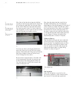
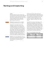
The breaker lifting device should be lifted into
position on top of the switchgear so that the
end with two rollers is toward the rear of the
—
69
—
72
—
73
—
70
—
71
—
69
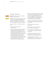
Removal of breaker lifting
device runner guide
—
70
Location of breaker
lifting device rear rollers
—
71
Front rollers positioned
on front track
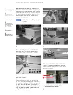
Before attempting to install the breaker lifting
device assembly on the switchgear equipment, it
is necessary to remove the runner guide from the
breaker lifting device carriage as shown in Figure
69. Do not dispose of this guide since it must be
reinstalled after mounting the breaker lifting
device on the equipment.
Notice:
Maximum lifting capacity is
700 lbs.
equipment, Figure 70.
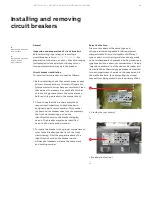
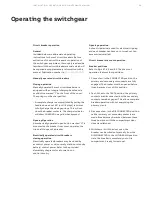
The rear wheels can then be hooked under the
channel and the front wheels can be positioned on
the front track. See Figure 71. The runner guide at
the rear should then be reassembled, Figure 72.
Stop blocks are provided at each end of the front
track to prevent the breaker lifting device from
rolling off the ends of the track.
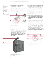
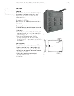
If the equipment has been shipped in sections,
Figure 74, there are splice plates for the runner
guide and breaker lifting device rail attached to
each respective part.
—
72
Replacing the runner
guide after completion
of breaker lifting
device installation
—
73
Removing the bracket
locking the dolly
—
74
Switchgear shipping
split front splice plate
1
2
—
74
1. Breaker lifting device rail splice plate
2. Splice plate mounting hardware
DANGER
WARNING
CAUTION
NOTICE


