40
I N S TA L L AT I O N , O P ER AT I O N S A N D M A I N T EN A N C E M A N UA L
Power cable connections
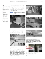
Connect the main cables to the main lugs.
Before any main cable connections are made,
the cables should be identified to indicate their
phase relationship with the equipment. Adequate
electrical and mechanical clearances must be
provided between conduit, cables, and bus. Where
the cables enter the section, they can be lashed to
optional cable supports at the rear of the cable
compartment as required.
Mechanical cable terminals are normally included
with the switchgear (compression terminals are
supplied when ordered) and are mounted at the
ends of the breaker runbacks in the cable
compartment. Carefully follow the cable
manufacturer's recommendations fo
installation of cable.
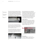
Install the cables in the proper path to the
terminals, using temporary lashing if required.
Cut the cables to the proper length. Strip the
insulation to the desired dimension, being
careful not to damage any strands.
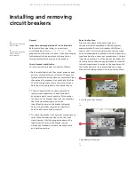
For copper cables, coat the wires with lubricating
grease, insert the cables into the terminals, and
tighten the set screws in accordance with torque
values shown in the torque value table for cable
terminals in the addendum of this manual. See
Appendix A, Table A.2.
For aluminum cables, wire brush the wire strands
thoroughly. Immediately after wire brushing, coat
the cable strands with a quality oxide inhibiting
compound such as Penetrox A. Insert exposed
wires into the terminals and tighten the set screws
in accordance with values shown in the torque
Table A.2 in Appendix A of this Instruction Book.
Caution:
The torque values shown in
the table are for dry threads only. Do
not grease or otherwise lubricate the
threads on the cable terminals as
this will permit over-tightening of
the screw and possible damage to
the terminal or cable.
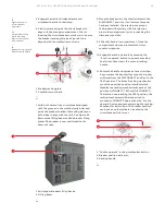
2. Route the control wires from the conduits
through the wiring trough (cross-hatched area-
2" x 7"-shown on Figure 65) at the side of the
cable compartment. Connect the cables to the
terminal blocks in accordance with the
connection diagrams for the equipment.
3. If the control conduits enter from above, drill the
top cover within the available space indicated.
See Figure 65. Control wires should be routed to
the wiring trough and connected to the terminal
blocks as described previously.
—
65
Control wire entry space
(indoor enclosure)
—
65
Equipment Depth
“A” (inches)
Direction
of Leads
“B”
54"
Below
19
Above
24
60"
Below
25
Above
30
67"
Below
32
Above
37
74"
Below
39
Above
44
Table 5 - Floor plan
DANGER
WARNING
CAUTION
NOTICE


