49
R E LI AG E A R® LV SG
LO W VO LTAG E S W I TC H G E A R
Key interlocks
After initial installation of the switchgear
equipment, all necessary interlock keys should be
inserted into the appropriate locks and all spare
keys should be stored in a location in accordance
with the owner's established procedures.
Caution:
Refer to the key interlock schematic
included in the summary furnished with the
equipment to determine the sequence of operation
and the correct number of operating keys required.
This precaution is necessary since the improper use
of spare keys will defeat the interlocking scheme.
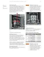
Breaker operation test
All compartments housing Emax 2 circuit breakers
have a TEST position in which the breaker primary
contacts are disconnected while the secondary
contacts are still engaged. This TEST position
permits complete testing of the electrical control
circuit without energizing the primary power
circuit. When the breaker is first put into service,
its control circuit must be thoroughly tested while
in this position to make sure that all closing and
tripping circuits are complete and functioning
properly. The TEST position is not suitable for
inspection and maintenance of the breaker and
should therefore be used only for testing breaker
operation. Refer to the appropriate breaker
instruction manual for other preoperational checks
on the breakers. See
Emax 2 trip units
The complete trip system is comprised of the
following components:
1. Solid-state Trip Unit with rating plug
2. Phase Current Sensors
3. Flux Shift Magnetic Trip Device
4. When applicable, a Neutral Sensor for units
containing a Ground Fault Trip element.
All components, except the Neutral Sensor, are
integrally mounted in the circuit breaker. When
used, the Neutral Sensor is separately mounted in
the bus or cable compartment of the switchgear.
In draw-out construction, it is automatically
connected to the trip unit in the breaker via
a draw-out secondary disconnect terminal.
Caution:
Never disengage the trip unit on a breaker
that is energized and carrying load current. This will
open-circuit the current sensors, allowing
dangerous and damaging voltages to develop.
Complete Instructions for testing the trip units
are included with the test set. The trip unit user
manuals are
Advanced Applications for Emax 2
Protections (ReliaGear LV SG only)
Reduced energy let through (RELT) -The RELT
functionality is achieved by leveraging the 2I
protection of the Emax 2 circuit breaker. The 2I
tripping curve is designed to mitigate against arc
flashes. This protection can be adjusted from 1.5 to
15 x In, with a maximum setting of 18kA. The
clearing time of the 2I protection is between 25 and
42ms at 60Hz (+5ms for 50Hz). Easy activation and
I/O assignment, including positive feedback, can
be implemented using the RELT Ekip Signalling 2K-3
module.
To learn more about the feature, please see
.
Prior to operation the 2I setting must be activated
and NEC 240.87 requires field testing be completed
for arc mitigation protections. Please see
for setup and test instruction.
For field testing of the RELT function:
• Step 1: Test position
Turn the RELT switch to the "TEST" position.
Observations to be made:
1. Pilot lamp will glow
2. Switch will return to the "NORMAL" state and
the Pilot lamp will turn off
• Step 2: ON position
Turn the RELT switch to "ON" position.
Observations to be made:
1. Pilot lamp will glow
2. Switch will remain in "ON" position
3. At the same time, the breaker trip unit will
keep flashing "2I Protection Active"
• Step 3: Normal position
Turn the RELT switch back to "NORMAL" position.
Observations to be made:
1. Pilot lamp will turn off and at that point there
will not by any indication on the breaker trip unit
For general wiring diagrams please see
.
For further wiring guidelines, please see
DANGER
WARNING
CAUTION
NOTICE


