27
R E LI AG E A R® LV SG
LO W VO LTAG E S W I TC H G E A R
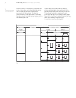
Space heaters, Figure 42 are provided as standard
equipment. They provide protection against
condensation of moisture that could, in
combination with air-borne contaminants,
deteriorate insulation or cause corrosion.
One 1000-watt, 240-volt, operating at 120V (250-
watts) AC heater is located on the floor of the bus
compartment of each outdoor switchgear section.
The heaters should be energized at all times to
prevent condensation within the switchgear.
Heaters are fed by the control power transformer.
The on-off control switch is located in the walk-in
front aisle.
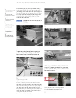
1. Run backs and cable lugs (compression type)
2. Space heater
Outdoor switchgear may also be provided without
the walk-in front aisle. Non-walk-in outdoor
equipment is not equipped with an overhead
breaker lifting device. A portable breaker lifting
device, available as an optional accessory, is used
for lifting the Emax 2 breakers.
—
42
Location of space heater
(indoor enclosure)
1
2
Outdoor switchgear
Switchgear designed for outdoor installations is
fully weatherproofed. See Figure 41. A
weatherproof housing completely encloses the
switchgear and may be provided with a walk-in
front aisle for easy access to all controls and
instruments.
Aisle lighting with wall switch, Figure 41, and a
115-volt GFCI convenience outlet are standard
devices supplied with front aisle outdoor
switchgear equipment. Also included in the walk-in
front aisle area are the breaker-lifting device and
storage provision for the breaker lifting device
operating crank as shown in Figure 41. A double-
wide door with panic latch is provided
for breaker loading.
1. Interior lighting switch
2. GFCI convenience outlet
3. Panic latch
4. Breaker lifting device crank
5. Walk-in aisle - 46 inches deep (approx.)
—
41
—
42
1
2
3
4
5
—
41
Switchgear outdoor
enclosure


