CHAPTER 4: SETPOINTS
PROTECTION
869 MOTOR PROTECTION SYSTEM – INSTRUCTION MANUAL
4–127
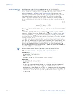
HOT/COLD SAFE STALL RATIO
Range: 0.01 to 1.00 in steps of 0.01
Default: 1
The motor manufacturer sometimes provide thermal limit information for a hot/cold
motor. The algorithm uses this data if this setting is programmed. The value entered for
the setting dictates the level at which Thermal Capacity Used settles for current that is
below the motor overload factor (OL) times FLA. When the motor is running at a level
that is below this limit Thermal Capacity Used rises or falls to a value based on I
eq
(thermal model biased motor load current). Thermal Capacity Used either rises at the
fixed rate of 5% per minute or falls as dictated by the running cool time constant.
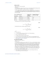
Eq. 19
where:
•
TCU
end
= Thermal Capacity Used, if I
eq
remains steady state.
•
I
eq
= equivalent motor heating current (also defined as Thermal Model Biased Motor
Load Current)
•
OL = Overload factor specified by the Motor Overload Factor setting.
•
FLA = Motor rated current specified by the Motor Full Load Amps setting.
•
hot/cold = Hot/Cold Safe Stall Ratio setting.
RTD BIAS
Range: Disabled, Enabled
Default: Disabled
When Enabled, this feature acts as an additional check of the motor overheating
through the current based thermal model. The current based thermal model estimates
motor heating from the thermal overload curves and cooling time constants. The
thermal overload curves are based solely on measured current, assuming a normal 40°C
ambient temperature and normal motor cooling. This feature provides additional
protection in cases where there is an unusually high ambient temperature, or motor
cooling is malfunctioning, or motor temperature increases due to other unexpected
factors, or the overload curve was selected incorrectly. Therefore, if the motor stator has
embedded RTDs, the RTD Bias feature is used to augment the thermal model calculation
of Thermal Capacity Used.This feature uses the hottest stator RTD temperature value to
estimate the RTD Thermal Capacity Used and compare this value to the Thermal
Capacity Used calculated by the current based thermal model (overload curve and cool
times). The larger of the two values is used from that point onward. Since RTDs have a
relatively slow response, RTD biasing is useful for slow motor heating. Other portions of
the thermal model are required during starting and heavy overload conditions when
motor heating is relatively fast
NOTE
NOTE:
1.
The RTD Bias feature is active only if the optional RTD Input module has been installed.
2.
Each stator RTD must be first configured as STATOR application under Setpoints/
Monitoring/RTD Temperature/RTD 1(X). RTDs configured as Stator type are used by the
thermal model for determining the RTD Bias.
3.
The RTD bias feature alone cannot generate a trip. Even if the RTD bias feature forces
the RTD bias thermal capacity used to 100%, the load current must be above the
overload pickup (OL x FLA) setting to set the output.
Содержание 869
Страница 10: ...VIII 869 MOTOR PROTECTION SYSTEM INSTRUCTION MANUAL ...
Страница 48: ...1 38 869 MOTOR PROTECTION SYSTEM INSTRUCTION MANUAL FOR FURTHER ASSISTANCE CHAPTER 1 INTRODUCTION ...
Страница 78: ...2 30 869 MOTOR PROTECTION SYSTEM INSTRUCTION MANUAL ELECTRICAL INSTALLATION CHAPTER 2 INSTALLATION ...
Страница 127: ...CHAPTER 3 INTERFACES SOFTWARE INTERFACE 869 MOTOR PROTECTION SYSTEM INSTRUCTION MANUAL 3 49 ...
Страница 129: ...CHAPTER 3 INTERFACES SOFTWARE INTERFACE 869 MOTOR PROTECTION SYSTEM INSTRUCTION MANUAL 3 51 ...
Страница 538: ...4 406 869 MOTOR PROTECTION SYSTEM INSTRUCTION MANUAL TESTING CHAPTER 4 SETPOINTS ...
Страница 578: ...6 22 869 MOTOR PROTECTION SYSTEM INSTRUCTION MANUAL FLEXELEMENTS CHAPTER 6 METERING ...
Страница 592: ...7 14 869 MOTOR PROTECTION SYSTEM INSTRUCTION MANUAL CLEAR RECORDS CHAPTER 7 RECORDS ...

