CHAPTER 4: SETPOINTS
PROTECTION
869 MOTOR PROTECTION SYSTEM – INSTRUCTION MANUAL
4–167
Underpower (37P)
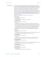
The Underpower element responds to total three-phase real power (kW) measured from
the phase currents and voltages. When the motor is in the running state, a trip and/or
alarm occurs once the magnitude of three-phase real power falls below the pickup level for
a period of time specified by the Trip Pickup Delay and/or Alarm Pickup Delay. The pickup
levels (Trip Pickup and Alarm Pickup) are based on the rated power obtained using
setpoints Motor Nameplate Voltage and Motor Full Load Amps, which are set under
Setpoints > System > Motor > Setup
. The pickup must be set lower than the lowest motor
loading during normal operations. For example, Underpower may be used to detect loss of
load conditions. Loss of load conditions does not always cause a significant loss of current.
Power is a more accurate representation of loading and may be used for more sensitive
detection of load loss or pump cavitation. This may be especially useful for detecting
process related problems.
Path:
Setpoints > Protection > Group 1(6) > Motor > Underpower
TRIP FUNCTION
Range: Disabled, Trip, Configurable
Default: Disabled
The setting enables the Underpower Trip functionality.
START BLOCK DELAY
Range: 0.00 to 15000.00 s in steps of 0.01 s
Default: 0.50 s
The setting specifies the length of time to block the Underpower function when the
motor is starting. The Underpower element is active only when the motor is running and
is blocked upon the initiation of a motor start for a period of time specified by this
setting. For example, this block may be used to allow pumps to build up head before the
Underpower element trips or alarms. A value of 0 specifies that the feature is not
blocked from start. For values other than 0, the feature is disabled when the motor is
stopped and also from the time a start is detected until the time entered expires.
TRIP PICKUP
Range: 1 to 25000 kW in steps of 1 kW
Default: 1 kW
The setting specifies a pickup threshold for the trip function. This setting is typically set
at a level less than the corresponding setting for the alarm function.
TRIP PICKUP DELAY
Range: 0.00 to 180.00 s in steps of 0.01 s
Default: 0.01 s
The setting specifies a time delay for the trip function. The time delay must be long
enough to overcome any short lowering of the load (e.g. during system faults).
TRIP DROPOUT DELAY
Range: 0.00 to 180.00 s in steps of 0.01 s
Default: 0.01 s
The setting specifies a time delay to reset the trip command. This delay must be set long
enough to allow the breaker or contactor to disconnect the motor.
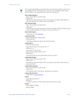
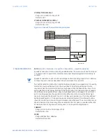
TRIP OUTPUT RELAY X
For details see
ALARM FUNCTION
Range: Disabled, Alarm, Latched Alarm
Default: Disabled
The setting enables the Underpower Alarm functionality.
Содержание 869
Страница 10: ...VIII 869 MOTOR PROTECTION SYSTEM INSTRUCTION MANUAL ...
Страница 48: ...1 38 869 MOTOR PROTECTION SYSTEM INSTRUCTION MANUAL FOR FURTHER ASSISTANCE CHAPTER 1 INTRODUCTION ...
Страница 78: ...2 30 869 MOTOR PROTECTION SYSTEM INSTRUCTION MANUAL ELECTRICAL INSTALLATION CHAPTER 2 INSTALLATION ...
Страница 127: ...CHAPTER 3 INTERFACES SOFTWARE INTERFACE 869 MOTOR PROTECTION SYSTEM INSTRUCTION MANUAL 3 49 ...
Страница 129: ...CHAPTER 3 INTERFACES SOFTWARE INTERFACE 869 MOTOR PROTECTION SYSTEM INSTRUCTION MANUAL 3 51 ...
Страница 538: ...4 406 869 MOTOR PROTECTION SYSTEM INSTRUCTION MANUAL TESTING CHAPTER 4 SETPOINTS ...
Страница 578: ...6 22 869 MOTOR PROTECTION SYSTEM INSTRUCTION MANUAL FLEXELEMENTS CHAPTER 6 METERING ...
Страница 592: ...7 14 869 MOTOR PROTECTION SYSTEM INSTRUCTION MANUAL CLEAR RECORDS CHAPTER 7 RECORDS ...

