4–220
869 MOTOR PROTECTION SYSTEM – INSTRUCTION MANUAL
PROTECTION
CHAPTER 4: SETPOINTS
Auxiliary
Undervoltage (27X)
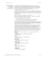
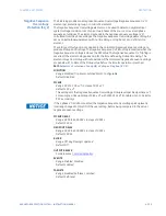
The 869 relay provides two identical Auxiliary Undervoltage (UV) elements per protection
group, or a total of 12 elements. Each Auxiliary Undervoltage element may be used to
protect voltage sensitive loads and system components against sustained undervoltage
conditions. This element may be used for permissive functions, initiation of the source
transfer schemes and similar functions.
The Auxiliary Undervoltage element may be set as an instantaneous element with no time
delay or as a time delayed element which can be programmed with definite time, inverse
time or FlexCurves. The Auxiliary Undervoltage element has a programmable minimum
operating threshold to prevent undesired operation when voltage is not available. The
input voltage is the auxiliary voltage.
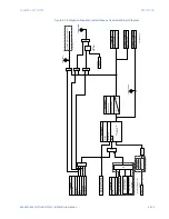
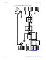
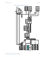
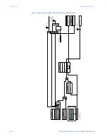
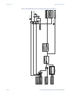
The settings of this function are applied to auxiliary voltage input to produce Pickup and
Trip flags. The Auxiliary UV Pickup flag is asserted when the auxiliary input voltage is below
the PKP value. The Auxiliary UV Trip flag is asserted if the element stays picked up for the
time defined by Pickup time delay or for the time defined by the selected inverse curve/
FlexCurve. The element drops from Pickup without operation if the measured voltage rises
above 102 to 103% of the Pickup value before the time for operation is reached.
The minimum voltage setting selects the operating voltage below which the element is
blocked (a setting of “0” will allow a dead source to be considered a fault condition).
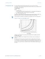
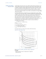
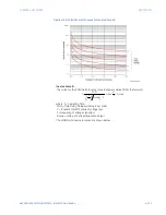
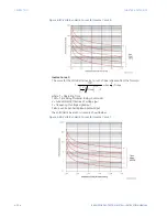
This element may be used to give a desired time-delay operating characteristic versus the
applied voltage, or as a definite time element. For the inverse time setpoint, the
undervoltage delay setpoint defines a family of curves as described in
.
Path
:
Setpoints > Protection > Group 1(6) > Voltage Elements > Auxiliary UV 1(X)
FUNCTION
Range: Disabled, Trip, Alarm, Latched Alarm, Configurable
Default: Disabled
PICKUP
Range: 0.00 to 1.50 x VT in steps of 0.01 x VT
Default: 1.00 x VT
This setting sets the Auxiliary Undervoltage Pickup level specified per times VT. For
example, a Pickup setting of 0.80 x VT with a 13800:115 VT translates into 11.04kV (or
92V secondary).
MINIMUM VOLTAGE
Range: 0.00 to 1.50 x VT in steps of 0.01 x VT
Default: 0.20 x VT
This setting sets the minimum operating voltage for the undervoltage Pickup level
specified per times VT.
UNDERVOLTAGE CURVES
Range: Definite Time, Inverse Time, FlexCurves A/B/C/D
Default: Definite Time
This setting provides the selection of definite time delay or time delay inverse
undervoltage curves. In the case of FlexCurves, the voltage ratio is reversed. For more
information refer to the equation and note regarding FlexCurves in
.
PICKUP DELAY
Range: 0.000 to 6000.000 s in steps of 0.001 s
Default: 1.000 s
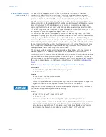
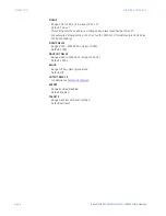
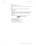
If
Inverse Time
is selected as an Undervoltage Curve setpoint, the Pickup Delay value is
loaded to variable D in the curve formula. For more information, refer to
Содержание 869
Страница 10: ...VIII 869 MOTOR PROTECTION SYSTEM INSTRUCTION MANUAL ...
Страница 48: ...1 38 869 MOTOR PROTECTION SYSTEM INSTRUCTION MANUAL FOR FURTHER ASSISTANCE CHAPTER 1 INTRODUCTION ...
Страница 78: ...2 30 869 MOTOR PROTECTION SYSTEM INSTRUCTION MANUAL ELECTRICAL INSTALLATION CHAPTER 2 INSTALLATION ...
Страница 127: ...CHAPTER 3 INTERFACES SOFTWARE INTERFACE 869 MOTOR PROTECTION SYSTEM INSTRUCTION MANUAL 3 49 ...
Страница 129: ...CHAPTER 3 INTERFACES SOFTWARE INTERFACE 869 MOTOR PROTECTION SYSTEM INSTRUCTION MANUAL 3 51 ...
Страница 538: ...4 406 869 MOTOR PROTECTION SYSTEM INSTRUCTION MANUAL TESTING CHAPTER 4 SETPOINTS ...
Страница 578: ...6 22 869 MOTOR PROTECTION SYSTEM INSTRUCTION MANUAL FLEXELEMENTS CHAPTER 6 METERING ...
Страница 592: ...7 14 869 MOTOR PROTECTION SYSTEM INSTRUCTION MANUAL CLEAR RECORDS CHAPTER 7 RECORDS ...


