4–94
869 MOTOR PROTECTION SYSTEM – INSTRUCTION MANUAL
INPUTS
CHAPTER 4: SETPOINTS
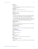
MAX VALUE
Range: -500000 to 500000 units in steps of 1 unit
Default: 0
For the MAXIMUM VALUE setpoint, enter the value which corresponds to the maximum
output value of the transducer. For example, if a temperature transducer which outputs
4 to 20 mA for temperatures 0 to 250°C is connected to the analog input, then enter
“250” for the MAXIMUM VALUE. The relay then interprets 20 mA as representing 250°C.
Intermediate values between the minimum and maximum are scaled linearly.
TRIP FUNCTION
Range: Disabled, Trip, Configurable
Default: Disabled
Selecting the Trip or Configurable setting enables the Trip function of the analog input. If
Disabled is selected, the main function still remains enabled and reads the meter value.
TRIP TYPE
Range: Over, Under
Default: Over
This setting determines if pickup occurs when the analog input is over or under the
programmed threshold.
TRIP PICKUP
Range: -500000 to 500000 units in steps of 1 unit
Default: 20
This setpoint provides the trip pickup level in the engineering units defined in the setting.
TRIP DROPOUT RATIO
Range: 2 to 20 in steps of 1%
Default: 5%
This setting represents the variation of pickup value, in percentage of pickup, at which
the element will effectively drop out. The drop out ratio is defined as follows:
•
Drop Out = pickup – pickup * dropout ratio /100, when TRIP TYPE is Over
•
Drop Out = pickup * dropout ratio /100, when TRIP TYPE is Under
For example, if the pickup level is 5000
µ
A, TRIP TYPE is set to “Over” and DROPOUT
RATIO set to “10%”, the actual dropout will be 4500
µ
A. Conversely, if the TRIP TYPE is
“Under” with the same dropout ratio, the actual dropout will be 5500
µ
A.
TRIP PICKUP DELAY
Range: 0 to 600 s in steps of 1 s
Default: 2
This setpoint will operate if the trip pickup condition is maintained for a longer time than
the delay time set here.
TRIP DROPOUT DELAY
Range: 0 to 600 s in steps of 1 s
Default: 0
This setpoint selects a fixed time interval to delay dropping out the output signal after
being generated.
TRIP OUTPUT RELAY X
For details see
ALARM FUNCTION
Range: Disabled, Alarm, Latched Alarm
Default: Disabled
The selection of Alarm or Latched Alarm setting enables the alarm function.
Содержание 869
Страница 10: ...VIII 869 MOTOR PROTECTION SYSTEM INSTRUCTION MANUAL ...
Страница 48: ...1 38 869 MOTOR PROTECTION SYSTEM INSTRUCTION MANUAL FOR FURTHER ASSISTANCE CHAPTER 1 INTRODUCTION ...
Страница 78: ...2 30 869 MOTOR PROTECTION SYSTEM INSTRUCTION MANUAL ELECTRICAL INSTALLATION CHAPTER 2 INSTALLATION ...
Страница 127: ...CHAPTER 3 INTERFACES SOFTWARE INTERFACE 869 MOTOR PROTECTION SYSTEM INSTRUCTION MANUAL 3 49 ...
Страница 129: ...CHAPTER 3 INTERFACES SOFTWARE INTERFACE 869 MOTOR PROTECTION SYSTEM INSTRUCTION MANUAL 3 51 ...
Страница 538: ...4 406 869 MOTOR PROTECTION SYSTEM INSTRUCTION MANUAL TESTING CHAPTER 4 SETPOINTS ...
Страница 578: ...6 22 869 MOTOR PROTECTION SYSTEM INSTRUCTION MANUAL FLEXELEMENTS CHAPTER 6 METERING ...
Страница 592: ...7 14 869 MOTOR PROTECTION SYSTEM INSTRUCTION MANUAL CLEAR RECORDS CHAPTER 7 RECORDS ...


