4–342
869 MOTOR PROTECTION SYSTEM – INSTRUCTION MANUAL
CONTROL
CHAPTER 4: SETPOINTS
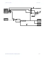
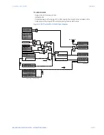
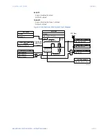
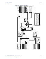
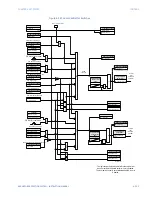
Figure 4-146: Restart Delay logic diagram
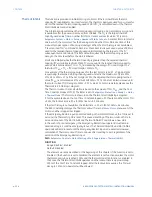
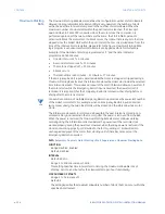
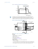
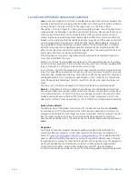
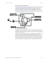
Reduced Voltage Starting
The 869 can control the transition of a reduced voltage starter from reduced to full voltage.
That transition may be based on “Current Only”, “Current and Timer”, or “Current or Timer”
(whichever comes first). When the 869 detects a 'Motor Starting' condition the current will
typically rise quickly to a value in excess of FLA (e.g., 5 × FLA). At this point, the Start Timer
is initialized while the motor current is simultaneously monitored. When the transition from
reduced to full voltage is initiated, the Reduced Volt Ctrl operand will be asserted for 1
second. The intention is to link this operand to the auxiliary output relay that can control
reduced voltage start contactors. The feature can also assert a trip signal if the current or
timer transitions do not occur as expected. This element is functional only if the external
motor Start/Stop command is used. An example of the control wiring related to this
element is depicted in the diagram,
Reduced Voltage Start Control Circuit
. A typical current
– time diagram of a reduced voltage start sequence is shown in
Voltage Start Current Characteristic
.
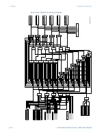
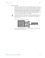
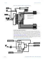
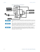
Figure 4-147: Reduced Voltage Start Contactor Control Circuit
894087A2.cdr
FLEXLOGIC OPERANDS
Restart Delay PKP
Function
SETPOINT
Enabled = 1
SETPOINT
FLEXLOGIC OPERANDS
Minimum Time
Restart Delay OP
ACTUAL VALUES
Restart Delay LO Time
Emergency Restart
FLEXLOGIC OPERAND
STATUS
Ti
m
e
r
Re
se
t
FLEXLOGIC OPERANDS
AN
D
Tmin
0
AN
D
LED: Start
Inhibit
Motor Stopped
Motor Tripped
OR
FLEXLOGIC OPERANDS
Start Inhibit
8940
$
1.cdr
CC 1
CC 2
869
Start
Inhibit
Relay
Trip
Relay
STOP
START
REDUCED VOLTAGE
CONTACTOR
FULL VOLTAGE
CONTACTOR
CC1
SEAL IN
869
Auxiliary
Relay
CC2 SEAL IN
Содержание 869
Страница 10: ...VIII 869 MOTOR PROTECTION SYSTEM INSTRUCTION MANUAL ...
Страница 48: ...1 38 869 MOTOR PROTECTION SYSTEM INSTRUCTION MANUAL FOR FURTHER ASSISTANCE CHAPTER 1 INTRODUCTION ...
Страница 78: ...2 30 869 MOTOR PROTECTION SYSTEM INSTRUCTION MANUAL ELECTRICAL INSTALLATION CHAPTER 2 INSTALLATION ...
Страница 127: ...CHAPTER 3 INTERFACES SOFTWARE INTERFACE 869 MOTOR PROTECTION SYSTEM INSTRUCTION MANUAL 3 49 ...
Страница 129: ...CHAPTER 3 INTERFACES SOFTWARE INTERFACE 869 MOTOR PROTECTION SYSTEM INSTRUCTION MANUAL 3 51 ...
Страница 538: ...4 406 869 MOTOR PROTECTION SYSTEM INSTRUCTION MANUAL TESTING CHAPTER 4 SETPOINTS ...
Страница 578: ...6 22 869 MOTOR PROTECTION SYSTEM INSTRUCTION MANUAL FLEXELEMENTS CHAPTER 6 METERING ...
Страница 592: ...7 14 869 MOTOR PROTECTION SYSTEM INSTRUCTION MANUAL CLEAR RECORDS CHAPTER 7 RECORDS ...


