


11
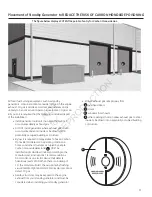
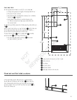
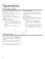
Placement of Standby Generator to REDUCE THE RISK OF CARBON MONOXIDE POISONING
The figure below displays POTENTIAL points of entry for Carbon Monoxide Gas.
All fossil fuel burning equipment, such as standby
generators, contains carbon monoxide (CO) gas in the engine
exhaust. CO gas is odorless, colorless and tasteless and is
unlikely to be noticed until a person is overcome. CO gas can
kill you so it is required that the following is included as part
of the installation:
• Install generator outdoors in an area that will not
accumulate deadly exhaust gas.
• DO NOT install generator where exhaust gas could
accumulate and enter inside or be drawn into a
potentially occupied building or structure.
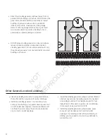
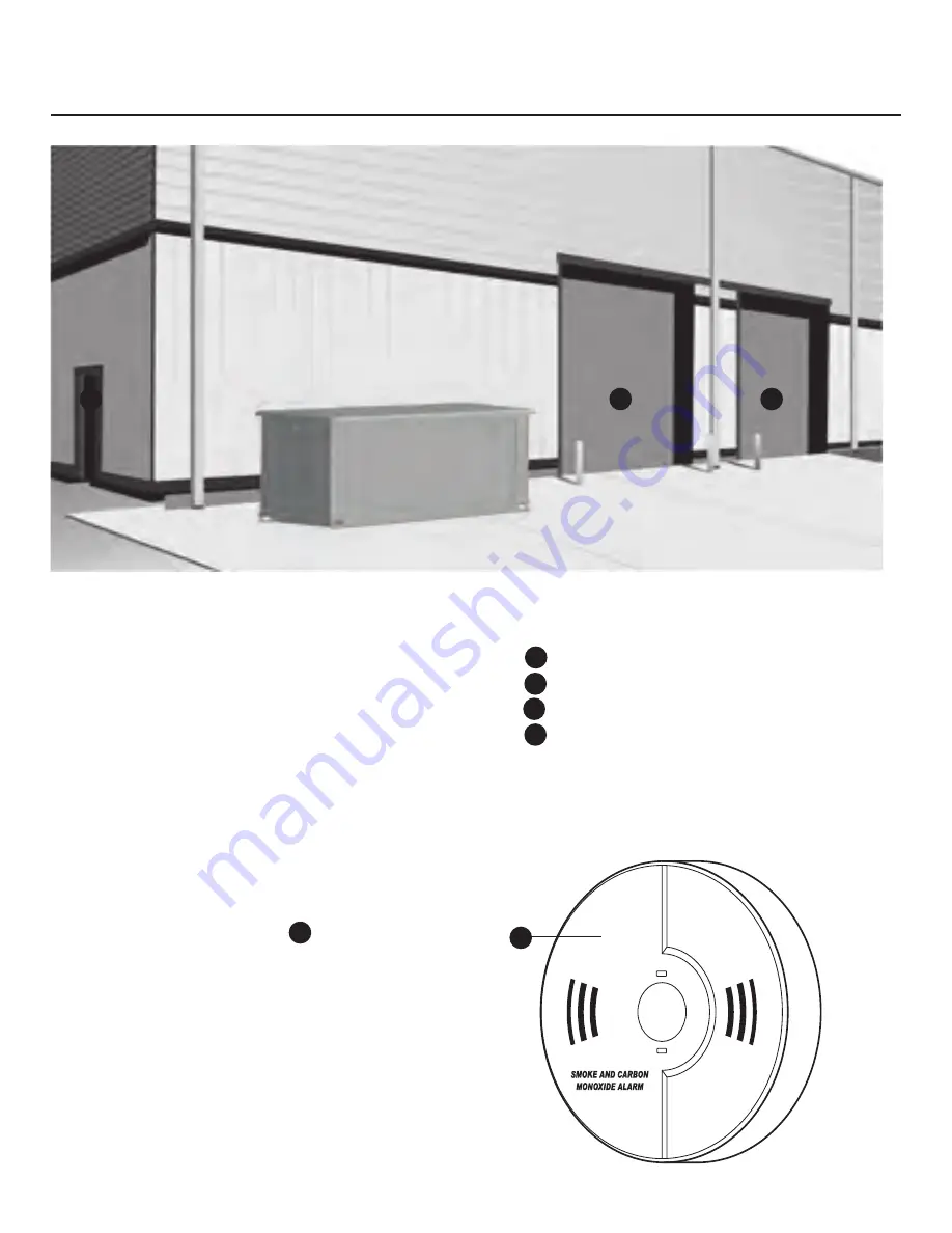
• By law it is required in many states to have a Carbon
Monoxide (CO) detector in operating condition in
homes and other structures occupied by people.
Carbon monoxide detector(s) (
A
) MUST be
installed and maintained indoors according to the
manufacturer’s instructions / recommendations.
A CO monitor is an electric device that detects
hazardous levels of CO. When there is a buildup of
CO, the monitor will alert the occupants by flashing
visual indicator light and alarm. Smoke alarms cannot
detect CO gas.
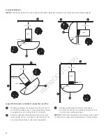
• Nearby structures may be exposed to the engine
exhaust from your standby generator and must be
considered when installing your standby generator.
• Ensure exhaust gas is kept away from:
B
overhead doors
C
doors
D
windows (not shown)
E
other openings that can allow exhaust gas to enter
inside or be drawn into a potenially occupied building
or structure.
A
A
B
C
D
E
B
B
C
NOT
for
REPRODUCTION
Содержание 60000 Series
Страница 28: ...28 Schematic Diagram Page 29 Page 31 Page 33 Page 30 Page 32 Page 34 N O T f o r R E P R O D U C T I O N...
Страница 31: ...31 Schematic Diagram continued YEL 18 BLK 18 GRY 20 YEL 18 BLK 14 N O T f o r R E P R O D U C T I O N...
Страница 33: ...33 Schematic Diagram continued GRY 20 YEL 18 GRN 20 YEL 20 BLK 14 N O T f o r R E P R O D U C T I O N...
Страница 35: ...35 N O T f o r R E P R O D U C T I O N...
Страница 36: ...36 Wiring Diagram ComAp InteliNano Control Panel N O T f o r R E P R O D U C T I O N...
Страница 37: ...37 Wiring Diagram ComAp InteliNano Control Panel N O T f o r R E P R O D U C T I O N...
Страница 38: ...38 Wiring Diagram ComAp InteliLite Control Panel N O T f o r R E P R O D U C T I O N...
Страница 39: ...39 Wiring Diagram ComAp InteliLite Control Panel N O T f o r R E P R O D U C T I O N...


