


17
CyScan Positioning System • Installation and Maintenance Guide r1.1
GCS
GCS
Maintenance and Servicing
The CyScan sensor is constructed from distinct modules that can be removed and re-
placed as required. This section covers the removal, replacement, upgrading and servicing
of the CyScan sensor system. A list of recommended spare parts is listed in Appendix 5.
Removing and fitting key components
There are nine key stages of disassembly/assembly for all CyScan sensor modules, these
are:
Stage
Previous stages required
1
The Rotor Heatshield
2
The Rotor
1
3
The Body Cover
1
4
The Motor Gearbox
1,2,3
5
The CPU Module
1,3
6
The Controller Board
1,3,5
7
The Yaw Gyro
1,2,3,4,5,6
8
The Vertical Reference Unit (VRU)
1,2,3,4
9
The Pitch and Roll Actuators
1,2,3,4
The figures shown to the right of each stage are the other previous stages that you must
complete before access can be gained to the necessary components.
!
WARNING: Ensure Static Safe Handling procedures are observed when removing/
fitting circuit board assemblies, e.g. CPU & Controller PCB, VRU, Yaw gyro, etc.
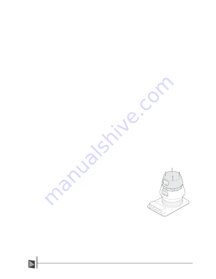
Stage 1 - The Rotor Heatshield
To remove the Rotor Heatshield:
1 Using a flat blade screwdriver, remove the
four screws on top of the rotor heatshield.
2 Lift the rotor heatshield up away from the
sensor.
To fit the Rotor Heatshield:
1 Place the rotor heatshield onto the rotor so
that the aperture aligns with the two rotor
lenses. Also the four mounting holes must
correspond to the four pillars on top of the
rotor.
2 Insert M5 x 12 slotted screws and bonded
seals into the four mounting holes and
using a flat blade screwdriver, tighten the
four screws in a staged and even manner
until all are tight.