


64
GETTING START-
ED
Using the GOTO
Key
MOB
The
man overboard feature
(MOB) is used in emergency situations, such as
man overboard, or to quickly mark a spot.
To turn on the MOB feature:
1. Press the
B
key.
2. Press the
T
key to confirm and begin navigating to the MOB position.
Once a MOB has been turned on, the MOB symbol will appear on the map dis-
play, and the destination field on the Map Page will display the bearing, distance,
and ETE to the MOB position based on your present speed and course.
To stop navigating to the MOB position:
1. Press the
G
key, followed by
O
, to display the GOTO options page.
2. Select the ‘Cancel GOTO’ option and press
T
.
TracBack Navigation
The third method of navigating to a destination is by
TracBack
. TracBack
allows you to retrace your path by using the track log automatically stored in the
receiver’s memory, which will eliminate the need to store waypoints along the way.
TracBack routes are created by reducing your track log into a route of up to 30
waypoints and activating an inverted route along those points.
To clear the track log and define a starting point for a TracBack route:
1. Press the
O
key twice to display the main menu page.
2. Highlight the ‘Track’ option and press
T
.
3. Select the ‘Delete Track?’ option and press
T
.
4. Highlight the ‘Yes’ field and press
T
.
To turn on a TracBack route:
1. Press the
G
key, followed by the
O
key. Highlight the ‘Start TracBack?’ option and
press
T
.
SECTION
8
GOTO/MOB
MOB and TracBack
Navigation
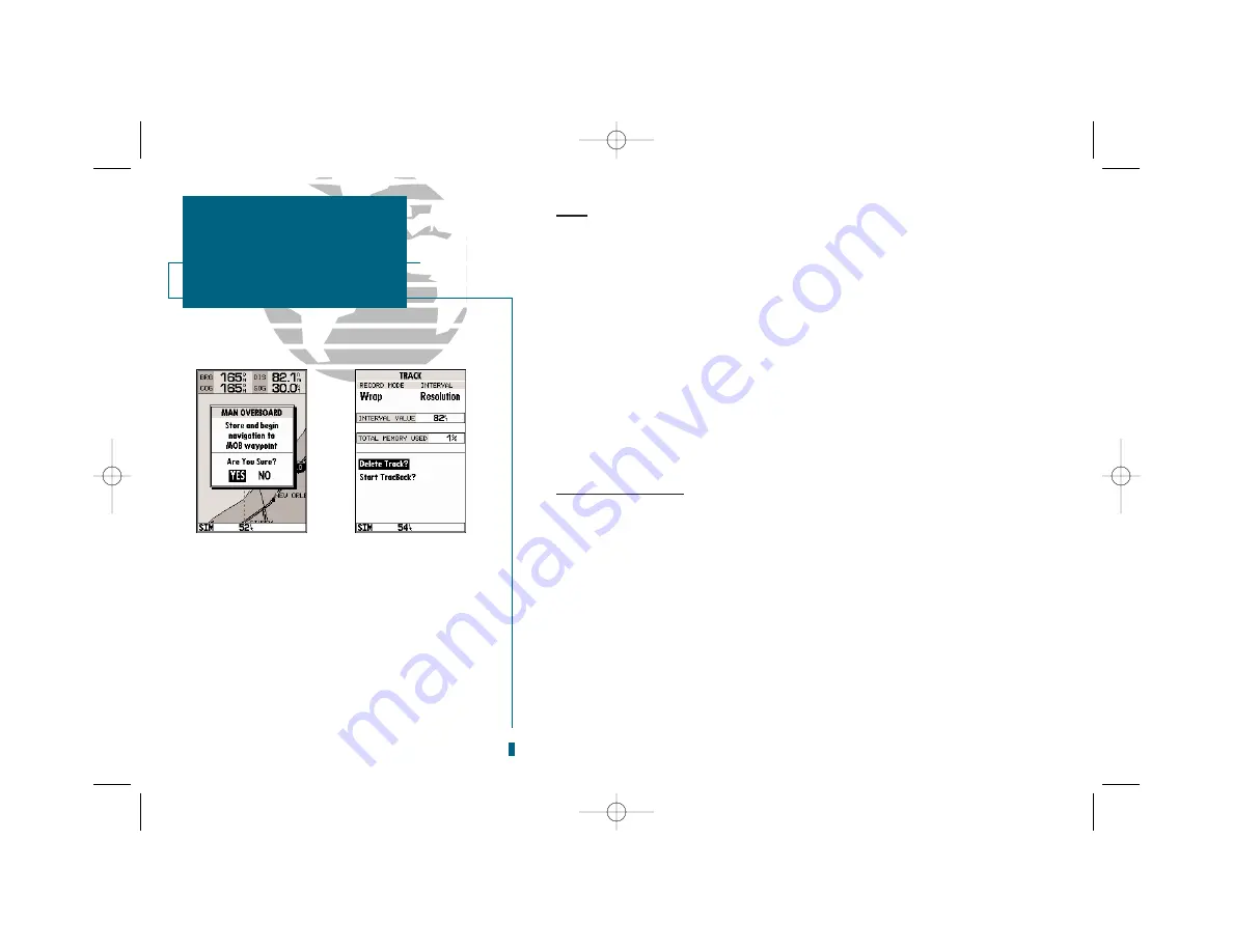
A
B
A.
The sounder’s MOB feature can be used to set a
course to a passing spot when a quick response to
emergency situations, fish strikes, etc. is needed.
B.
To define a starting point for a TracBack route, first
clear the track log.
19000138.10A.QXD 11/11/99 8:47 AM Page 64