190-01717-B1
G500/G600 TXi Part 23 AML STC Maintenance Manual
Rev. 1
Page 5-44
11. Change the airspeed until the PFD airspeed tape pointer is at the top of the green band/bottom of
the yellow band (Vno).
12. Verify that the top of the green arc/band on the standby ASI and PFD airspeed tape are at the same
airspeed value.
13. Increase the airspeed to the upper red radial/top of yellow arc (Vne).
14. Verify that the red radial on the standby ASI and PFD airspeed tape are at the same airspeed value.
15. Starting at the current airspeed, decrease the airspeed to zero, stopping at each of the airspeeds
listed in Table 5-3 (airspeeds above Vne should not be checked), verifying that the PFD and
standby ASI airspeed values are within the tolerances indicated in Table 5-3.
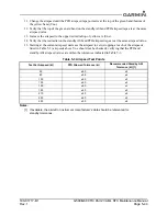
Table 5-3 Airspeed Test Points
Notes:
[1] If available, the aircraft or instrument manufacturer’s data should be referenced for
standby tolerances.
Test Set Airspeed (kt)
PFD Allowed Tolerance (kt)
Recommended Standby ASI
Tolerance (kt) [1]
50
±5.0
±5
80
±3.5
±4
100
±2.0
±3
120
±2.0
±3
150
±2.0
±3
180
±2.0
±5
210
±2.0
±5
250
±2.0
±5
290
±3.0
±6

