190-01717-B1
G500/G600 TXi Part 23 AML STC Maintenance Manual
Rev. 1
Page 5-5
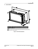
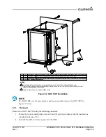
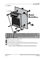
3. Remove the four(4) screws retaining the GDU in the instrument panel shown as item 1 in figure 5-
1 or figure 5-2 above.
4. Gently pull the GDU out from the instrument panel far enough to access the cable connectors and
ADC module (if installed).
5. Remove the cable connectors from the back of the GDU.
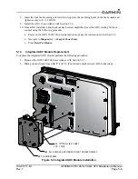
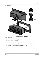
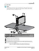
6. If an integrated ADAHRS is installed in the GDU, Loosen the four(4) thumbscrews securing the
ADC module to the rear of the GDU as shown in figure 5-3 below and gently separate the module
from the GDU. If the ADC module is being replaced, proceed to Section 5.1.3.
5.1.2
Cooling Fan Replacement
NOTE
The GDU cooling fan replacement kit (P/N: K00-01080-00) must be obtained from an
authorized Garmin dealer. In order for the GDU warranty to remain valid this procedure
must be accomplished by an authorized Garmin dealer.
NOTE
Resetting the fan operation hours requires the use of an Installer unlock card.
The GDU 1060/700 cooling fan has a recommended replacement interval of 3000 hours. After 3000 hours
of operation the cooling fan should be replaced using the following procedure:
1. Remove the GDU from the instrument panel in accordance with Section 5.1.1.
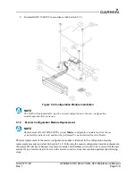
2. Remove the four(4) screws securing the fan module to the rear of the GDU and discard the o-rings.
3. Grasp the fan module and gently pull the module out of the GDU.
4. Visually inspect the inside of the fan module receptacle on the back of the GDU for the following:
◦
Verify that the four rubber gaskets around the fan screw mounting holes and are not torn,
damaged, or missing. If any of these conditions are found replace all four gaskets(not
included in fan replacement kit).
◦
Inspect the 4-pin electrical connector for the fan module for damage or corrosion. If any
damage is found, return the GDU to Garmin for service.
5. Place the new o-rings included in the fan replacement kit on the four fan mounting screws.
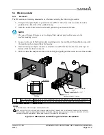
6. Place the new cooling fan module in the fan well of the GDU with the electrical connector oriented
on the upper side near the J7 connector.
CAUTION
It may be necessary to slightly move the fan module within the fan well to align the
connector pins and connector body. If the module does not press into the back of the GDU
with slight pressure, the connector may not be aligned. If the connector cannot be aligned,
remove the module again and inspect the pins on the fan module and the connector on the
GDU for straightness or damage. Applying too much pressure to the fan module with the
connector out of alignment could cause damage to the fan module, GDU connector, or
both.
7. Slide the fan module evenly into the fan well on the GDU and gently press the module into the
back of the GDU.

