190-01717-B1
G500/G600 TXi Part 23 AML STC Maintenance Manual
Rev. 1
Page 5-6
8. Insert the four fan mounting screws with o-rings into the mounting holes on the fan module and
tighten evenly to 8 ± 1 LBF-IN.
9. Install the GDU in accordance with Section 5.1.6.
10. Once GDU installation and checkout has been accomplished, reset the GDU cooling fan hour
counter using the following procedure:
a. Power on the GDU 1060/700 in configuration mode per the instructions in Section 2.1.4.
b. Navigate to
Diagnostics
→
Temp & Power Stats.
c. Press
Reset Fan Hours.
5.1.3
Integrated ADC Module Replacement
To replace the integrated ADC module perform the following procedure:
1. Remove the GDU 1060/700 in accordance with Section 5.1.1.
2. Mark pitot and static lines with ‘P’ and ‘S’, if not already marked, near ADC connections.
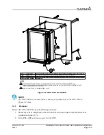
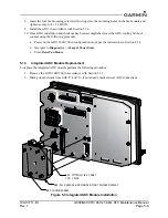
Figure 5-3 Integrated ADC Module Installation
REF. FITTING, 1/8-27 ANPT
TYP. 2 PLCS
REF. 011-03457-00 ADC MODULE, GDU 700/1060 DISPLAY
REF. THUMB SCREW

