190-01717-B1
G500/G600 TXi Part 23 AML STC Maintenance Manual
Rev. 1
Page 5-11
5.2.2
Re-Installation
NOTE
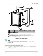
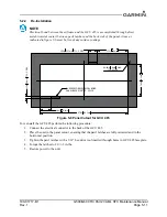
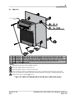
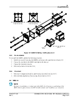
Electrical bond between the airframe and the GCU 485 is accomplished through direct
metal-to-metal contact between pawl latches and the back side of the panel. Areas as
indicated in figure 5-6 must be free of any surface coatings.
Figure 5-6 Panel Cutout for GCU 485
To re-install the GCU 485 perform the following procedure:
1. Connect the electrical connector to the back of the GCU 485.
2. Place the unit in the panel cutout, ensuring that the pawl latches are fully retracted and in the
horizontal position.
3. Tighten the pawl latches with a 3/32” hex drive tool inserted through holes in GCU 485 face plate.
4. Torque the latches to 20 +/-2 in-lbs.
5. Restore power to the unit.
1.780in
45.2mm
4.970in 126.2mm
R0.06in 1.6mm MAX.
TYP. 4 PLCS
1.73in 44mm
0.50in 12.7mm TYP. 2 PLCS
0.64in 16.3mm
0.15in
3.8mm
TYP. 2 PLCS
SURFACE FOR ELECTRICAL BOND
PANEL BACK SIDE TYP. 2 PLCS

