Page 33 of 35
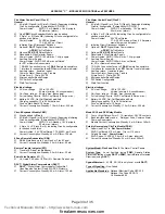
APPENDIX "C" - MODULE SPECIFICATIONS and FEATURES
Fire Alarm Control Panel (Flex 4)
General:
M
4 Style B (Class B) or 2 Style D (Class A) Supervised Initiating
Circuits; configurable. [Compatibility ID “GWC01”]
Power Limited:
26VDC, 3 mA standby, 1.5Vp-p ripple,
50 mA max. (alarm)
M
One
CEM
Circuit Expander Module may be added.
M
2 Style Y or Z (Class A/B) Indicating Circuits; configurable for
strobes or audibles.
Power Limited:
24 VDC unfiltered
1.7 A @ 49C per Circuit
M
Initiating Circuit Disconnect Switches.
M
Optional
DACT
Digital Alarm Communicator
or
PRM
City Tie Module.
M
Optional
RY4 / RY8
Relay Module.
M
Resettable 4-Wire Detector Supply.
Power Limited:
28VDC, 100mA max, 1.5Vp-p ripple
M
Auxiliary Power Supply.
Power Limited:
24VDC, 300mA max, unfiltered
for RTI or Remote Annunciators
M
1 RS-485 Connection for up to 3
RA8
Remote Annunciators.
M
1
Interface for connection to an
RTI
Remote Trouble Indicator.
M
Auxiliary relays: (resistive loads)
Common Alarm, Supervisory, Trouble
All are Form C, 1Amp, 28VDC
M
Micro-controller Based Design.
M
DIP Switch Configurable.
M
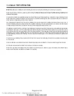
Walk-Test function.
Electrical ratings:
M
AC Line Voltage:
102 to 132 VAC.
4 Amps (primary, 4A circuit breaker)
M
Pwr Supp. ratings:
6 Amps. max. (secondary)
M
For Indicating Circuits: 24VDC unfiltered (5 Amps. max.)
M
Battery:
24VDC, Gel-Cell/Sealed Lead-Acid
Charging capability:
10 to 24 AH batteries
Fuse on Main Board:
10 Amps.
M
Current Consumption:
Standby: 110 mA, Alarm: 220 mA
Circuit Expander Module
CEM)
M
May be added to
Flex 4
.
M
4 Style B (Class B) or 2 Style D (Class A) Supervised Initiating
Circuits; configurable. [Compatibility ID “GWC01”]
Power Limited:
22VDC, 3 mA standby, 1.5Vp-p ripple,
50 mA max. (alarm)
M
2 Style Y or Z (Class B or A) Indicating Circuits; configurable
for strobes or audibles.
Power Limited:
24 VDC unfiltered, 1.7A @49C per Circuit
M
Current Consumption: Standby:
45 mA,
Alarm:
120 mA
8 Zone Remote Annunciator (RA8)
M
RS-485 Interface, up to 3 per Flex 4 or Flex 8 Panel.
M
Current Consumption:
Standby: 35 mA, Alarm: 90 mA
Remote Trouble Indicator (RTI)
M
Trouble LED and Trouble Buzzer
M
Current Consumption:
Standby: 35 mA, Alarm: 35 mA
End-of-Line Resistor
(30177)
M
UL Listed 3.9 Kohm, 1/2 Watt, 5% Resistor. Spade Lugs
DACT / Digital Alarm Communicator (DACT)
M
DACT
- “Digital Alarm Communicator Transmitter”
Uses Ademco Contact ID and SIA-DCS Protocols.
M
Current Consumption: Standby:
45 mA,
Alarm:
120 mA
Fire Alarm Control Panel (Flex 8)
General:
M
8 Style B (Class B) or 4 Style D (Class A) Supervised Initiating
Circuits; configurable. [Compatibility ID “GWC01”]
Power Limited:
26VDC, 3 mA standby, 1.5Vp-p ripple,
50 mA max. (alarm)
M
4 Style Y or Z (Class A/B) Indicating Circuits; configurable for
strobes or audibles.
Power Limited:
24 VDC unfiltered
1.7 A @ 49C max per Circuit 5 Amperes
maximum per control panell
M
Initiating Circuit Disconnect Switches.
M
Optional
DACT
Digital Alarm Communicator
or
PRM
City Tie Module.
M
Optional
RY4 / RY8
Relay Module.
M
Resettable 4-Wire Detector Supply.
Power Limited:
28VDC, 100mA max, 1.5Vp-p ripple
M
Auxiliary Power Supply.
Power Limited:
24VDC, 300mA max, unfiltered
for RTI or Remote Annunciators
M
1 RS-485 Connection for up to 3
RA8
Remote Annunciators.
M
1 Interface for connection to an
RTI
Remote Trouble Indicator.
M
Auxiliary relays: (resistive loads)
Common Alarm, Supervisory, Trouble
All are Form C, 1Amp, 28VDC
M
Micro-controller Based Design.
M
DIP Switch Configurable.
M
Walk-Test function.
Electrical ratings:
M
AC Line Voltage:
102 to 132 VAC.
4 Amps (primary, 4A circuit breaker)
M
Pwr Supp. ratings:
6 Amps. max. (secondary)
M
For Indicating Circuits: 24VDC unfiltered (5 Amps. max.)
M
Battery:
24VDC, Gel-Cell/Sealed Lead-Acid
Charging capability:
10 to 24 AH batteries
Fuse on Main Board:
10 Amps.
M
Current Consumption:
Standby: 110 mA, Alarm: 220 mA
Model:
RY4 and RY8
Relay Module
M
Four or Eight Relays: Form C, 1A (resistive), 28 VDC contacts
M
Each individual relay can be:
Relay per Zone, Common Alarm,
Common Supervisory
M
Module Current Consumption:
Standby:
5 mA,
Alarm:
160 mA
Polarity Reversal and City Tie Module
(PRM)
M
Supervised City Tie
Not Power Limited
24VDC unfiltered, 210 mA max.,
Trip coil:
14 ohms
M
Polarity Reversal
Power Limted
24VDC open, 12VDC @ 3.5 mA, 8 mA max. (shorted)
M
Current Consumption: Standby:
35 mA,
Alarm:
300 mA
System Model:
Flex 4 and Flex 8
Fire Alarm Control Panels
System Type:
Local, Auxiliary (using
PRM
), Remote Station
Protected Premises (using
DACT
or
PRM
), Central Station Protected
Premises (using
DACT
).
Type of Service:
A, M, WF, SS (SS is only Local or with
DACT
)
Type of Signalling:
Non-Coded
Applicable Standards:
National Electrical Code NFPA 70
National Fire Code NFPA 72
UL Standard 864
Technical Manuals Online! - http://www.tech-man.com
firealarmresources.com

