background image

Page 26 of  35

9.2  CONTROLS:

System Reset Switch:

The System Reset momentary switch causes the Fire Alarm Control Panel, and all Circuits, to be reset ...

Resets all Latching Trouble Conditions

Resets all Initiating Circuits

Interrupts the 4-Wire Detector Supply

Turns off all Indicating Circuits

Turns off Signal Silence Indicator

Turns off Fire Drill

Stops and resets all Timers

Processes inputs as new events

Aux Disconnect not affected

Signal Silence Switch:

Activation of the Signal Silence momentary switch when the Panel is in Alarm turns on the Signal Silence

Indicator and deactivates any Silenceable Indicating Circuits. Non-Silenceable Circuits are unaffected. Signals

will re-sound upon any subsequent Alarm. This switch does not function during any configured Signal Silence

Inhibit Timer period. It also does not function if the Indicating Circuits are active as the result of a Fire Drill.

Fire Drill Switch:

The Fire Drill momentary switch activates all non-Disconnected Indicating Circuits, but does not transmit any
Alarms via the Dialler, City Tie, or Common Alarm Relay, nor are any 

RY4

 or 

RY8

 Relays activated. Fire Drill

is cancelled by activating the switch again, or if the Panel goes into a real Alarm.

Auxiliary Disconnect Switch:

Activating the Auxiliary Disconnect momentary switch activates the Auxiliary Disconnect function. Activating

the switch again de-activates the function. When Auxiliary Disconnect is active, Common Alarm and  Common
Supervisory Relays, and any 

RY4

 / 

RY8

 Relays are not activated. The Trouble Relay is activated. Digital Alarm

Communicator (

DACT

)  or City Tie Modules (

PRM

) are also inactive if installed, except that a Trouble condition

is transmitted.

Lamp Test Switch:

Activation of the Lamp Test momentary switch turns all front panel Indicators and the buzzer on.

Buzzer Silence Switch:

Activation of the Buzzer Silence momentary switch while the Buzzer is sounding silences the Buzzer.  The

Buzzer will resound if there is a subsequent event.

Circuit Disconnect Switches:

Activation of these non-momentary switches disconnects the respective Initiating Circuit, and causes a Circuit

Trouble for that Initiating Circuit while active. If the disconnect switch is turned off (to its normal position) while

there is an Alarm condition in that circuit, the respective circuit Status LED will flash at a rate of 120 flashes per

minute to indicate a Pending Alarm, for 5 seconds. If the disconnect switch is not turned back on, an Alarm will

be processed normally.

9.3 OPERATION:

All Alarm inputs are treated in a similar manner.  Alarm inputs include Non-Verified or Verified Alarms, and Water-
flow Alarms. Any of these Alarm inputs occurring when the Panel is not already in Alarm cause the following:

Ž

The Buzzer sounds steadily

Ž

If Fire Drill is active, it is cancelled

Ž

The Common Alarm Indicator turns on

Ž

The Common Alarm Relay activates if Aux Disconnect is not active

Ž

The Auto Signal Silence Timer, if configured, starts

Ž

The Signal Silence Inhibit Timer, if configured, starts

Ž

RY4 / RY8 Relays are activated as configured, provided that Aux Disconnect is not active

Ž

Signals and Strobes are activated

Subsequent Alarms when the Panel is already in Alarm, cause the following:

Ž

The Buzzer sounds steadily 

Ž

If Signals have been silenced as a result of the Signal Silence button or the Auto Signal Silence Timer, Signals are resounded as they were
before Signal Silence, the Signal Silence Indicator is turned off, and the Auto Signal Silence Timer, if configured, is restarted

Ž

Signals and Strobes are activated

Technical Manuals Online! - http://www.tech-man.com

firealarmresources.com

Содержание Flex 4

Страница 1: ...N MANUAL Notice All information Documentation and Specifications contained in this manual are subject to change without prior notice by the manufacturer 1999 by The Gamewell Company Part Number 71954 Issue B 07 19 2001 Technical Manuals Online http www tech man com firealarmresources com ...

Страница 2: ...7 of 32 7 5 DACT DIGITAL ALARM COMMUNICATOR MODULE TERMINAL CONNECTIONS Page 18 of 32 7 6 POLARITY REVERSAL and CITY TIE MODULE MODEL PRM TERMINAL CONNECTIONS Page 18 of 32 7 7 POWER SUPPLY CONNECTIONS Page 19 of 32 WIRING TABLE FOR INITIATING CIRCUITS Page 20 of 32 WIRING TABLE FOR INDICATING NOTIFICATION APPLIANCE CIRCUITS Page 20 of 32 8 0 SYSTEM CHECKOUT Page 21 of 32 8 1 BEFORE TURNING THE PO...

Страница 3: ... General Field Wiring Considerations Page 13 of 32 Fig 9 Main Fire Alarm Module Terminal Connections Page 14 of 32 Fig 9a Main Fire Alarm Module Terminal Connections continued Page 15 of 32 Fig 10 CEM Circuit Expander Module Terminal Connections Page 16 of 32 Fig 11 RY4 RY8 Relay Terminal Connections Page 17 of 32 Fig 12 PRM Polarity Reversal and City Tie Module Terminal Connections Page 18 of 32 ...

Страница 4: ...t is configurable for Normal or Verified Alarm operation On a Flex 4 configured for Class B wiring performance or on a Flex 8 configured for Class A Initiating Circuit 3 may be configured as a Waterflow Zone and Initiating Circuit 4 may be configured as a Latching or Non Latching Supervisory Zone On a Flex 8 also Flex 4 with the optional CEM module installed configured for Class B wiring operation...

Страница 5: ...e Circuits Signal Circuits and Bell Circuits Wiring Styles Initiating Circuits are configured by default as Class B Style B They may be GLOBALLY all or none configured as Class A Style D as described in the Configuration Section This operation uses odd and even pairs of two wire Class B Style B circuits to make one four wire Class A Style D circuit thus halving the number of available Initiating C...

Страница 6: ... 4 Flex 8 Fire Alarm Control Model CEM Circuit Expander Module Model PRM Polarity Reversal City Tie Module Model DACT Digital Communicator Module Model RY4 RY8 4 8 Relay Module Technical Manuals Online http www tech man com firealarmresources com ...

Страница 7: ...ote Trouble Indicator RTI and or 1 to 3 of RA8 Remote Multiplex Annunciators Resettable Power Supply for Four Wire Smoke or Heat Detectors May have one DACT or PRM and one CEM installed May also have one of RY4 or RY8 installed Model CEM Circuit Expander Module for the Flex 4 to increase the system capacity to that of the Flex 8 Model RY4 Relay Module for Flex 4 or Flex 8 Adds four configurable Re...

Страница 8: ... 8 15 16 5 16 14 3 11 1 2 14 1 5 4 3 1 2 1 1 7 8 14 1 8 1 7 8 KNOCKOUT 122 1 8 3 1 2 8 3 4 2 6 x 5 16 SCREW MATERIAL BACKBOX 18GA 0 048 THICK Fig 1 Flex 4 and Flex 8 Enclosure Installation and Dimensions 4 0 MECHANICAL INSTALLATION and DIMENSIONS Install the enclosure as shown below for the Flex 4 and Flex 8 Technical Manuals Online http www tech man com firealarmresources com ...

Страница 9: ...ATIONS The Flex 4 and Flex 8 come pre assembled with all components and boards except for the following optional modules DACT PRM RY4 RY8 or the CEM when field installed to increase the circuits available with the Flex 4 The modules are installed in the locations shown below Be sure to connect a solid Earth Ground from building system ground to a cold water pipe to the Chassis Earth Ground Mountin...

Страница 10: ... P6 P7 Relay Module Remove jumper JW3 if a RY4 or RY8 Relay Module is installed The Relay Module is plugged into P1 Digital Communicator Remove jumper JW6 if a DACT Digital Communicator is installed The Digital Communicator is plugged into P8 City Tie Remove jumper JW6 if a PRM Polarity Reversal City Tie module is installed The module is plugged into P8 Battery Connected to P2 ve P3 ve via the fac...

Страница 11: ... Circuit Class B Style B operation and from 2 to 3 for Class A Style D operation Note that the Class A B selection affects all Initiating Circuits and must be used with the correct Configuration DIP Switch Setting P1 P2 Connections to P7 P6 respectively on the Main Fire Alarm Board SW5 6 Configuration DIP Switches Technical Manuals Online http www tech man com firealarmresources com ...

Страница 12: ... Common Supervisory Relay by moving the jumper from JW1 to JW1A etc These jumpers have two positions to select Alarm or Supervisory each JW1A Alarm or Supv control for Relay 1 JW2A Alarm or Supv control for Relay 2 JW8A Alarm or Supv control for Relay 8 Finally there are jumpers JW1 2 JW2 3 up to JW7 8 that allow a relay to have the same control as an adjacent relay For example starting with the f...

Страница 13: ...more information 6 5 POLARITY REVERSAL and CITY TIE MODULE MODEL PRM P1 Cable to P8 on the Main Fire Alarm Module JW1 Cut this jumper for Trouble transmission When this jumper is cut and a system trouble occurs the designated terminals will transmit a zero volts or open circuit Please note that at normal condition the terminals polarity is read exactly as labelled on the circuit board Jumper JW6 o...

Страница 14: ...E FIELD WIRING 7 1 GENERAL FIELD WIRING CONSIDERATIONS Because most of the Field Wiring on the Flex 4 and Flex 8 is to the Main Board s on the swinging Dead Front panel it is very important to properly dress the wires so as not to place stress on either their connection to the boards or running to conduit The figure below shows the required wiring techniques Technical Manuals Online http www tech ...

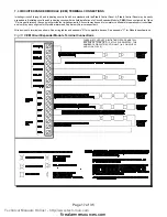
Страница 15: ...IS CUT IN HALF i e 2 ON A FLEX 4 AND 4 ON A FLEX 8 7 2 MAIN FIRE ALARM MODULE TERMINAL CONNECTIONS Wire devices to terminals as shown See wiring tables and Appendix A for compatible devices and Appendix C for specifications Caution Do not exceed power supply ratings Total current for Indicating Circuits is 5 A max Technical Manuals Online http www tech man com firealarmresources com ...

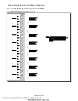
Страница 16: ...Page 16 of 35 Fig 9a Main Fire Alarm Module Terminal Connections continued Technical Manuals Online http www tech man com firealarmresources com ...

Страница 17: ...ontrol Panel may be easily expanded to 8 initiating circuits and 4 indicating circuits with the field installation of a Circuit Expander Module CEM When configured for Class A wiring performance the control will provide four initiating circuits All circuits may be used for normal or verified alarm operation or circuits three and four may be configured for Waterflow alarm and Supervisory Service re...

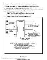
Страница 18: ...5 7 4 RELAY MODULE RY4 or RY8 TERMINAL CONNECTIONS Note that only Relays 1 to 4 are present on the RY4 Fig 11 RY4 RY8 Relay Terminal Connections Technical Manuals Online http www tech man com firealarmresources com ...

Страница 19: ...TIONS See Appendix for Module specifications Wire as shown using proper wire gauges Note that for use in the USA the installer MUST add an Atlantic Scientific Tel 407 725 8000 Model 24544 Protective Device or a similar UL Listed QVRG Secondary Protector as shown Note The Terminal Blocks are pluggable for ease of wiring The City Tie Interface is Not Power Limited Either the City Tie or Reverse Pola...

Страница 20: ... Flex 4 and Flex 8 Electrical input ratings 120 VAC 60 Hz 2 A main primary circuit breaker Power supply total current 6 A maximum Battery Fuse on Main Module F1 Replace with 10 Amp 1 1 4 Fast Acting Fuse CAUTION Do not exceed power supply ratings See appendix C for specifications Wire as shown using proper wire gauges Technical Manuals Online http www tech man com firealarmresources com ...

Страница 21: ...3000 915 4250 1296 15 0 30 470 143 750 229 1200 366 1900 579 6 0 60 235 71 375 114 600 183 850 259 3 0 90 156 47 250 76 400 122 570 174 2 1 20 118 36 185 56 300 91 425 129 1 5 1 50 94 29 150 46 240 73 343 105 1 2 1 70 78 24 125 38 200 61 285 87 1 0 RS 485 WIRING See the Connection Diagram AUXILIARY POWER FOR The maximum allowable current is 0 15 Amperes The maximum allowed FOUR WIRE TYPE DETECTORS...

Страница 22: ...rmittently and the Common Trouble LED should flash 3 Connect the batteries Observe correct polarity The red wire is positive and black wire is negative 4 All indicators should extinguish except for normal power AC ON green LED 5 Configure the Fire Alarm Control Panel as described in the Configuration section 8 3 TROUBLESHOOTING Circuit Trouble Normally when a Circuit trouble occurs its designated ...

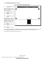
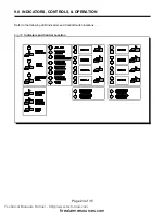
Страница 23: ...35 Fig 16 Indicators and Control Location 9 0 INDICATORS CONTROLS OPERATION Refer to the following LED Indicators and Control Switch locations Technical Manuals Online http www tech man com firealarmresources com ...

Страница 24: ...re is communication trouble detected with a Remote Annunciator RA8 or if a Remote Annunciator reports a local trouble It is turned off if these conditions go away Fire Drill LED The Fire Drill Indicator turns on steady Amber while Fire Drill is active Auxiliary Disconnect LED The Auxiliary Disconnect Indicator is flashed Amber 20 flashes per minute when the Auxiliary Disconnect switch is activated...

Страница 25: ...ouble for Initiating and Indicating Circuits They illuminate Slow Flashing Amber 20 flashes per minute for any field wiring fault or if the circuit has been Disconnected Technical Manuals Online http www tech man com firealarmresources com ...

Страница 26: ...ivation of the Lamp Test momentary switch turns all front panel Indicators and the buzzer on Buzzer Silence Switch Activation of the Buzzer Silence momentary switch while the Buzzer is sounding silences the Buzzer The Buzzer will resound if there is a subsequent event Circuit Disconnect Switches Activation of these non momentary switches disconnects the respective Initiating Circuit and causes a C...

Страница 27: ...m is confirmed and processed An Alarm condition causes the associated Circuit Status LED and the Common Alarm LED to illuminate Red Note Do not use Retard Operation with any external Retarding device maximum Retard may not exceed 120 seconds Non Latching Supervisory For Supervisory Devices Circuits 4 8 only An activation on these circuits will cause the Circuit Status LED and the Common Supervisor...

Страница 28: ...On 100 of the time Temporal Code 3 of 5 second on 5 second off 1 5 second pause March Code 5 second on 5 second off California Code 5 second on 10 second off Technical Manuals Online http www tech man com firealarmresources com ...

Страница 29: ... 4 off 3 on 5 Minutes 4 on 3 off 10 Minutes 4 on 3 on 20 Minutes Switch 9 4 Signal Silence Inhibit Switch 9 5 None 1 Minute Initiating Circuit Style Class Switch 9 6 Class B Style B Class A Style D Auxiliary Devices Switch 9 7 Non Silenceable Silenceable AC Power Fail Delay to Aux Devices Switch 9 8 24 Hour Standby Standard 60 Hour Standby Standard Notes AFTER ANY CONFIGURATION SWITCHES ARE CHANGE...

Страница 30: ...O PERFORM A SYSTEM RESET Only Indicating Circuit 4 may be configured for Visual Devices If Initiating Circuit 7 is configured as Waterflow the corresponding Verified selection becomes a Retard selection Note Do not use Retard Operation with any external Retarding device maximum Retard may not exceed 120 seconds If Initiating Circuit 8 is configured as Alarm the corresponding Latching selection has...

Страница 31: ...ed the Indicating Circuits will sound for three bursts with additional activations sounding for one burst etc The initial burst interval denoting the count of the Circuit number is one second on and one half a second off corresponding to the Circuit being tested The subsequent burst interval denoting additional activations on the same Initiating Circuit is one half second on then off After the sou...

Страница 32: ...eparately powered alarm initiating device e g smoke or heat detector having an operating voltage range equal to or exceeding the output of the Flex 4 or Flex 8 and having a dry contact for alarm initiating is electrically compatible Be certain to install a end of line Listed power supervision module after the electrically last initiating device on each circuit For ease in trouble determination use...

Страница 33: ...gital Alarm Communicator Transmitter Uses Ademco Contact ID and SIA DCS Protocols M Current Consumption Standby 45 mA Alarm 120 mA Fire Alarm Control Panel Flex 8 General M 8 Style B Class B or 4 Style D Class A Supervised Initiating Circuits configurable Compatibility ID GWC01 Power Limited 26VDC 3 mA standby 1 5Vp p ripple 50 mA max alarm M 4 Style Y or Z Class A B Indicating Circuits configurab...

Страница 34: ... Smoke Detector X 0 000110 0 052 71034 or 30954 Ion Smoke Detector X 0 000081 0 052 71035 or 71035 160 or 71035 210 Heat Detector X 0 000057 0 052 71443 Combination Photo Heat Detector X 0 000185 0 052 Signal Load bells horns strobes and etc Auxiliary Power Supply for Annunciators etc ALARM Total currents Add above currents STANDBY A B Total Current Requirement ALARM B ______ Amps Battery Capacity...

Страница 35: ...e responsible to repair or replace equipment which has been repaired by others abused improperly installed altered or otherwise misused or damaged in any way Unless previously contracted by Gamewell Gamewell will assume no responsibility for determining the defective or operative status at the point of installation and will accept no liability beyond the repair or replacement of the product at our...

Отзывы: