


Page 29 of 35
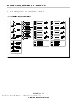
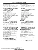
10.0 MODULE SYSTEM CONFIGURATION
Configuration of the
Flex 4
and
Flex 8
Control Panels is easily accomplished by DIP Switch and Jumper Settings.
For DIP Switches, 0 = switch “off”, 1 = Switch “on’).
On the
Main Fire Alarm Board
...
Function
DIP Switch
Switch “Off”
Switch “On”
Indicating Circuit #1
Audible Device (Bell) Only
Switch 13, #1
Silenceable
Non-Silenceable
Indicating Circuit #2
Audible or Visual Device
Switch 13, #2
Silenceable
Non-Silenceable
Switch 13, #3
Audible Device (Bell/Horn)
Visual Device (Strobe)
# Remote Annunciators
Switch 13, #4
5 off, 4 off = None
5 off, 4 on = One
5 on, 4 off = Two
5 on, 4 on = Three
Switch 13, #5
Manual Signal Silence
Switch 13, #6
Disabled
Enabled
Fire Drill
Switch 13, #7
Disabled
Enabled
Auxiliary Disconnect
Switch 13, #8
Disabled
Enabled
Initiating Circuit #1
Alarm Only
Switch 11, #1
Normal Alarm
Verified Alarm
Initiating Circuit #2
Alarm Only
Switch 11, #2
Normal Alarm
Verified Alarm
Initiating Circuit #3
Alarm or Waterflow
Switch 11, #3
Normal
Verified Alarm / Retarded Waterflow
Switch 11, #4
Alarm
Waterflow
Initiating Circuit #4
Alarm or Supervisory
Switch 11, #5
Normal
Verified Alarm (no effect on Supv.)
Switch 11, #6
Alarm
Supervisory
Switch 11, #7
Non-Latching Supervisory
(No effect on Alarm)
Latching Supervisory
(No effect on Alarm)
Not Used
Switch 11, #8
-----------------
-----------------
Signal Code
Switch 9, #1
2 off, 1 off = Temporal Code
2 off, 1 on = Continuous
2 on, 1 off = March Time
2 on, 1 on = California Code
Switch 9, #2
Auto Signal Silence
Switch 9, #3
4 off, 3 off = Disabled
4 off, 3 on = 5 Minutes
4 on, 3 off = 10 Minutes
4 on, 3 on = 20 Minutes
Switch 9, #4
Signal Silence Inhibit
Switch 9, #5
None
1 Minute
Initiating Circuit Style / Class
Switch 9, #6
Class B (Style B)
Class A (Style D)
Auxiliary Devices
Switch 9, #7
Non-Silenceable
Silenceable
AC Power Fail Delay to
Aux. Devices
Switch 9, #8
24 Hour Standby
Standard
60 Hour Standby
Standard
Notes:
&
AFTER ANY CONFIGURATION SWITCHES ARE CHANGED, IT IS NECESSARY TO PERFORM A SYSTEM RESET !!
&
Only Indicating Circuit 2 may be configured for Visual Devices.
&
If Initiating Circuit 3 is configured as Waterflow, the corresponding Verified selection becomes a Retard
selection.
Note: Do not use Retard Operation with any external Retarding device; maximum Retard may not exceed 120
seconds.
&
If Initiating Circuit 4 is configured as Alarm, the corresponding Latching selection has no effect.
&
If Initiating Circuit 4 is configured as Supervisory, the corresponding Verified selection has no effect.
&
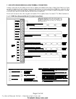
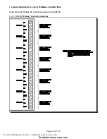
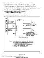
The selection of Class A/B (Style Z/Y) Indicating Circuits is only a matter of how they are wired. No Programming
is necessary See Connection Information (
Figures 9 & 10
).
&
If Class A (Style D) Initiating Circuits are selected, the appropriate Board Jumpers must also be set.
Class B Initiating Circuits 1 & 2 combine to create Class A Circuit #1, and Class B Initiating Circuits 3 & 4
combine to create Class A Circuit #2.
In Class A operation, the DIP Switches for Circuits 3 & 4 are ignored except for an
Flex 4
with a
CEM
Circuit
Expander Module. LED Indicators for Circuits 3 & 4 are non-functional except for an
Flex 4
with a
CEM
Circuit
Expander Module.
Technical Manuals Online! - http://www.tech-man.com
firealarmresources.com


