


Page 10 of 35
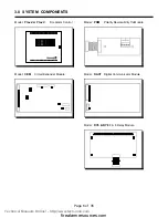
6.0 MODULE SETTINGS
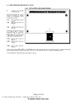
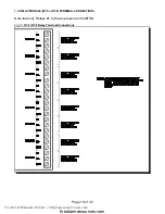
6.1 MAIN FIRE ALARM MODULE
Class A / B Selection:
JW1
&
JW2
are connected from 1 to 2 for Initiating Circuit
Class B (Style B)
operation, and from 2 to 3 for
Class
A (Style D)
operation.
Note that the Class A/B selection affects all Initiating Circuits, and must be used with the correct Configuration DIP Switch Setting.
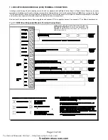
Circuit Expander
On an
Flex 4
only, remove the jumper on
JW4
if a
CEM
Circuit Expander Module is field installed. The module
Module:
is plugged into
P6 & P7
.
Relay Module:
Remove jumper
JW3
if a
RY4
or
RY8
Relay Module is installed. The Relay Module is plugged into
P1
.
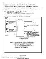
Digital Communicator:
Remove jumper
JW6
if a
DACT
Digital Communicator is installed. The Digital Communicator is plugged into
P8
.
City Tie:
Remove jumper
JW6
if a
PRM
Polarity Reversal/City Tie module is installed. The module is plugged into
P8
.
Battery:
Connected to
P2 (+’ve)
&
P3 (-’ve)
via the factory installed cables.
Transformer:
Factory wired to
P4
&
P5
, do not disconnect.
JW5
There should be no jumper here; do not use.
SW9, SW11, SW13
Configuration DIP Switches.
Battery Fuse F1:
Replace with 10 Amp, 1-1/4" Fast Acting Fuse
Technical Manuals Online! - http://www.tech-man.com
firealarmresources.com


