


Page 11 of 35
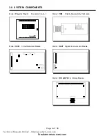
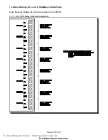
Fig.3:
Main Fire Alarm Module
Fig.4:
CEM Circuit Expander Module
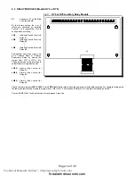
6.2 CIRCUIT EXPANDER MODULE (Model CEM)
Class A / B Selection:
JW2 & JW3
are connected from 1 to 2 for Initiating
Circuit Class B (Style B) operation,
and from 2 to 3 for Class A (Style D)
operation.
Note that the Class A/B selection
affects all Initiating Circuits, and
must be used with the correct
Configuration DIP Switch Setting.
P1
&
P2:
Connections to P7 & P6
respectively on the Main
Fire Alarm Board.
SW5,6:
Configuration DIP Switches.
Technical Manuals Online! - http://www.tech-man.com
firealarmresources.com


