Page 15 of 35
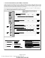
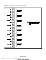
Fig.9:
Main Fire Alarm Module Terminal Connections
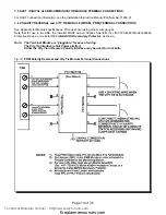
CLASS A / STYLE D NOTE: INITIATING CIRCUITS MUST
ALL BE EITHER STYLE B OR D. IF STYLE D IS
SELECTED, THE NUMBER OF CIRCUITS IS CUT IN
HALF. (i.e. 2 ON A FLEX 4 AND 4 ON A FLEX 8)
7.2 MAIN FIRE ALARM MODULE TERMINAL CONNECTIONS
Wire devices to terminals as shown. See wiring tables and
Appendix A
for compatible devices and
Appendix C
for specifications.
Caution:
Do not exceed power supply ratings: Total current for Indicating Circuits is 5 A max.
Technical Manuals Online! - http://www.tech-man.com
firealarmresources.com


