


Page 17 of 35
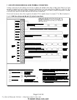
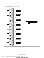
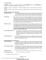
Fig.10:
CEM Circuit Expander Module Terminal Connections
CLASS A / STYLE D NOTE: INITIATING CIRCUITS MUST ALL
BE EITHER STYLE B OR D. IF STYLE D IS SELECTED, THE
NUMBER OF CIRCUITS IS CUT IN HALF. (i.e. 2 ON A FLEX 4
AND 4 ON A FLEX 8)
7.3 CIRCUIT EXPANDER MODULE (CEM) TERMINAL CONNECTIONS
Initiating circuits 5 through 8 and Indicating circuits 3 and 4 are standard with the
Flex 8
Control Panel. A
Flex 4
Control Panel may be easily
expanded to 8 initiating circuits and 4 indicating circuits with the field installation of a Circuit Expander Module (
CEM
). When configured for Class
“A” wiring performance, the control will provide four initiating circuits. All circuits may be used for normal or verified alarm operation or circuits three
and four may be configured for Waterflow alarm and Supervisory Service respectively.
Wire devices to terminals as shown. See wiring tables and appendix "A" for compatible devices. See appendix "C" for Module specifications.
Technical Manuals Online! - http://www.tech-man.com
firealarmresources.com


