


Page 4 of 35
1.0 INTRODUCTION
The
Gamewell
Flex 4
Fire Alarm Control Panel
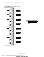
provides four supervised Class B (Style B) Initiating Circuits, or
two supervised Class A (Style D) Initiating Circuits, and two supervised Class A or B (Style Z or Y) Indicating Circuits.
The
Gamewell
Flex 8
Fire Alarm Control Panel
provides eight supervised Class B (Style B) Initiating Circuits, or
four supervised Class A (Style D) Initiating Circuits, and four supervised Class A or B (Style Z or Y) Indicating
Circuits. All Circuits are supervised for opens and ground faults, and Indicating Circuits also for shorts.
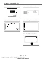
Available options include; a
Circuit Expander Module (
CEM
) to increase the
Flex 4
to a
Flex 8
, a Digital Alarm
Communicator Module (
DACT
) or a Polarity Reversal / City Tie Module (
PRM
), and two auxiliary relay modules,
Model
RY4
and Model
RY8
that provide four or eight configurable Form C dry contacts respectively.
1.1 Overall Features:
T
The
Flex 4
has 4 Class B (Style B) Initiating Circuits which may be configured as 2 Class
A (Style D) Circuits. The
Flex 4
has 2 power limited Class A/B (Style Z/Y) Indicating
Circuits with an individual trouble indicators for each circuit. A
CEM
, Circuit Expander
Module can be easily field installed to increase the circuit capacity of a Flex 4 to that of the
Flex 8.
T
The
Flex 8
has 8 Class B (Style B) Initiating Circuits which may be configured as 4 Class A (Style D)
Circuits. The
Flex 8
has 4 power limited Class A/B (Style Z/Y) Indicating Circuits with an individual trouble
indicators for each circuit.
T
Each Initiating Circuit is configurable for Normal or Verified Alarm operation. On a
Flex 4
configured for
Class B wiring performance (or on a
Flex 8
configured for Class A), Initiating Circuit 3 may be configured
as a Waterflow Zone and Initiating Circuit 4 may be configured as a Latching or Non-Latching Supervisory
Zone.
On a
Flex 8
(also
Flex 4
with the optional
CEM
module installed) configured for Class B wiring operation,
Initiating Circuit 3 and/or Initiating Circuit 7 may be configured as a Waterflow Zone, and Initiating Circuit
4 and/or Initiating Circuit 8 may be a Latched or Non-Latched Supervisory Zone.
T
Indicating Circuits may be configured as Audible or Visual and as silenceable or non-silenceable. Circuits
configured for audible devices may operate for Steady, Temporal Code, California Code, or March Time.
T
Individual Slide-Switch provided for disconnect of each initiating circuit.
T
Signal Silence Inhibit (disabled or 1 minute) and Auto Signal Silence (disabled or 5, 10, 20 minutes)
T
Zone Annunciated Walk Test.
T
Subsequent Alarm, Supervisory, and Trouble Operation.
T
Resettable Auxiliary Power Supply (200 mA Max.) For Four Wired Smoke Detectors
T
Auxiliary contacts for Common Alarm and Supervisory (disconnectable), and Common Trouble relay.
T
RS-485 Interface for up to 3
RA8
Multiplexed Remote Annunciators.
T
Remote Trouble Indicator Interface for
RTI
T
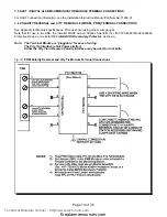
Accepts an optional
DACT
(Dialler) or
PRM
(City Tie) module, and also one
RY4
or
RY8
Relay Module.
T
Easy Configuration via DIP Switches.
T
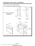
Rugged, key locked, red cabinet with ten combination knockouts, easily removeable piano hinged door and
an integrated trim “ring” for surface or flush mounted installation. Uses Gamewell Key.
Technical Manuals Online! - http://www.tech-man.com
firealarmresources.com


