VES, LLC eView Installation Manual VF3510-00, Revision E01.06 Issue Date: 10/16/2009
eView Installation Manual
Страница 1: ...VES LLC eView Installation Manual VF3510 00 Revision E01 06 Issue Date 10 16 2009 eView Installation Manual...
Страница 2: ...Net eNET and firmware reference from first paragraph of Section 2 Overview Re drafted this paragraph to include reference to the buzzer annunciation and silence the front panel controls the use of lev...
Страница 3: ...ncy energy and if not installed and used in accordance with the Installation Manual may cause harmful interference to radio communications Operation of this equipment in a residential area is likely t...
Страница 4: ...Installation Manual VF3510 00 Revision E01 06 All other product or service names are the property of their respective owners VES is a registered trademark of VES LLC Copyright 2009 by VES LLC All rig...
Страница 5: ...ed 3 Warranty Returns 3 Advanced Replacements 4 Suspect Product Testing 4 Product Return Address 4 Section 2 Overview Controls and Indicators 6 Controls 7 Indicators 9 Section 3 Installation Before Yo...
Страница 6: ...Contents ii VES LLC eView Installation Manual VF3510 00 Revision E01 06 Appendix A Specifications Electrical 16 Communications 16 Operating Environment 16 Physical Specifications 16...
Страница 7: ...Contents iii VES LLC eView Installation Manual VF3510 00 Revision E01 06 This page intentionally left blank...
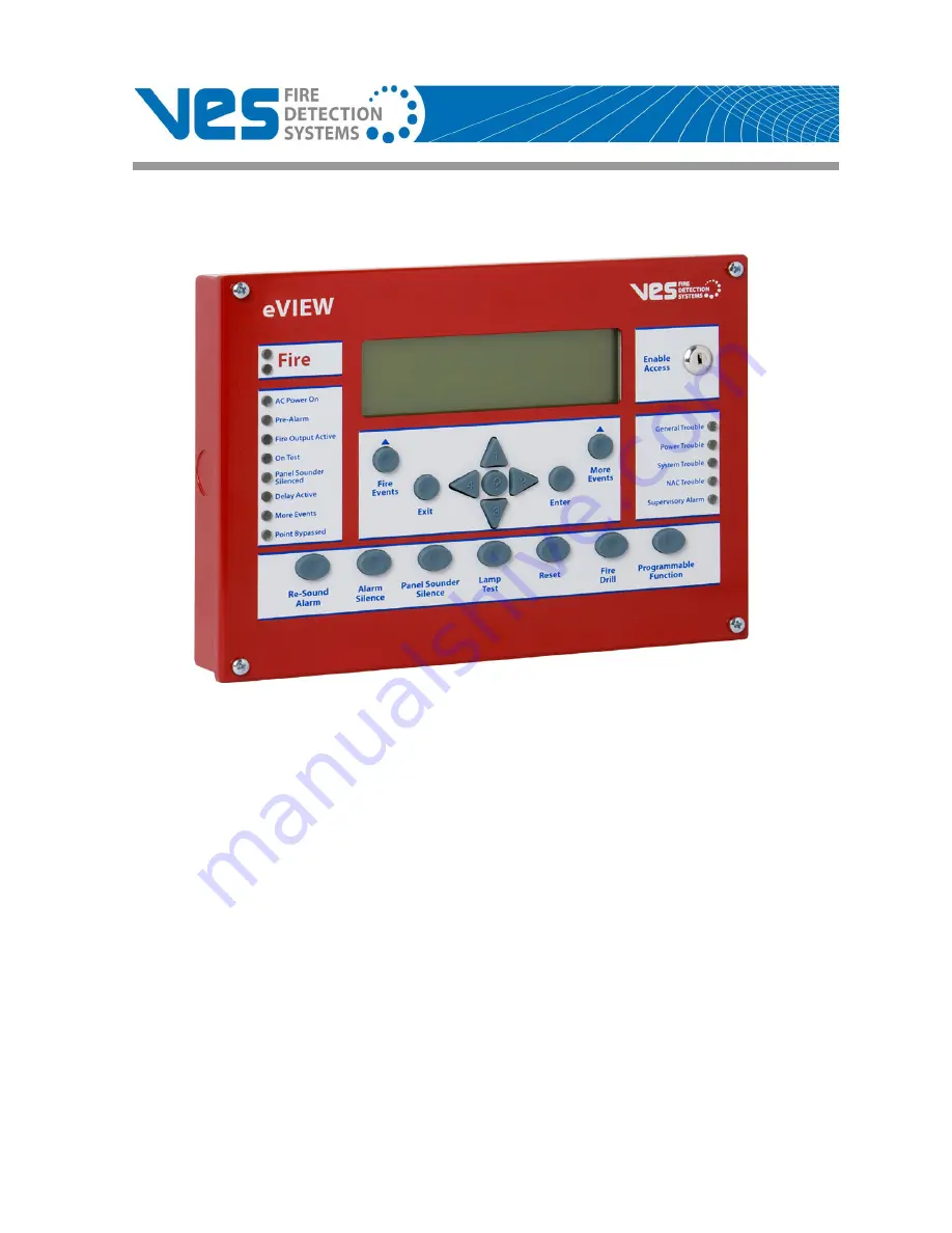
Страница 8: ...trim ring kit VF1173 00 This section describes Using This Manual Related Documentation Document Conventions If You Need Help Contacting VES For Repair The figure below illustrates the front panel of...
Страница 9: ...mbers Part numbers are provided in Section 1 and Appendix B of this manual Refer to Appendix B Equipment List for a complete list of part numbers required for completing this installation Writing styl...
Страница 10: ...ing information collected from the on site technician VES cannot not accept product returns that do not include an accompanying RMA number An RMA number is assigned when A product issue is acknowledge...
Страница 11: ...ed at the request of the contractor Shipping costs associated with this process are the responsibility of the contractor Returning Products Suspect products returning to VES using the advanced replace...
Страница 12: ...Introduction 1 VES LLC eView Installation Manual VF3510 00 Revision E01 06 5 of 16 This page intentionally left blank...
Страница 13: ...tion of Level 2 on multiple eViews Operate Level 2 on one eView at a time when multiple eViews are connected on the RS485 communication path The buzzer of the eView can annunciate and silence in uniso...
Страница 14: ...ncels the current menu selection 4 Central keypad question mark Provides a help screen for the current menu display and also dis plays status For example recommendations are displayed during alarm or...
Страница 15: ...panel display and sounding the buzzer 5 Reset Resets latching inputs such as fire and pre alarm events after receiving authorization through Access Level 2 Fault events are non latching inputs and ca...
Страница 16: ...olor 1 Fire NAC Output State Flashing NACs Activated ON Continuous NACs silenced OFF Panel and NACs Reset Red 2 Fire NAC Output State Flashing NACs Activated ON Continuous NACs silenced OFF Panel and...
Страница 17: ...er The eView should not be mounted in the proximity of heat sources or placed inside enclosures that do not have ade quate ventilation Cables should be connected using suitable cable connections If ad...
Страница 18: ...e front of the eView circuit board Wiring must be dressed away from the eView circuit board when cabling enters the enclosure at locations other than the knockouts Data Termination Up to 15 devices ca...
Страница 19: ...8 PR3 NETWORK OUT 1 2 3 4 5 6 7 8 9 10 11 12 13 14 15 16 17 18 19 20 21 22 23 OUT OUT NC C NO OUT IN LOOP4 OUT IN IN LOOP 3 OUT IN IN LOOP 2 OUT IN IN LOOP 1 OUT IN NC C NO TROUBLE FIRE1 NC C NO FIRE2...
Страница 20: ...ctions 1 Remove four screws from the front panel of the eView 2 Remove the rear cover 3 Connect RS485 communication to the terminals of COMM1 4 Connect 24 VDC power to terminals of 0V and 24V Key Name...
Страница 21: ...ated a different address The switch settings for each of the addresses are shown below Figure 3 5 illustrates binary addresses 1 to 15 on the eView Figure 3 5 Binary Addresses The black portion of the...
Страница 22: ...fault signal is provided to the eLAN or Elite Panel when the eView is being subjected to continuous interference Press the W DOG RESET button on the bottom of the PCB if a processor re start occurs Th...
Страница 23: ...om the Aux 24V terminals RS485 SERIAL BUS RS485 two wire Maximum distance from control panel 3900 feet 1200 meters Specify Belden 9271 cable MAXIMUM NUMBER OF UNITS The eLAN and Elite can each support...
Страница 24: ...16 VES LLC eView Installation Manual VF3510 00 Revision E01 06...