G
AMATRONIC
E
LECTRONIC
I
NDUSTRIES
L
TD
.
CENTRIC User Guide, rel. 3.4
61
7.2.9.1.2
U
SING THE INPUT DRY CONTACTS
The connection for each input dry contact consists of two pins – one independent pin (AUX1, AUX2, AUX3,
AUX4, or AUX5), and the second pin, labeled COM (or COMMON).
Input dry contact AUX5 makes use of an opto-coupler.
No more than 30 V and 100 mA should be
applied to input dry contact AUX5. Exceeding either of these limits may cause serious damage to
the system controller.
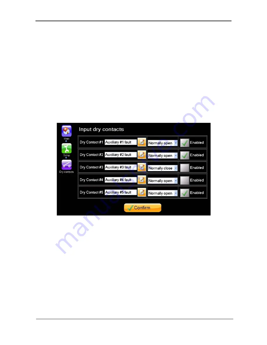
In the "Setup > Dry contacts > Input dry contacts screen the user defines the dry contact as normally open
or normally closed, depending on the normal state of the external circuit. The user must also ensure that
the input dry contact is enabled, by selecting the "Enabled" box for that dry contact in the same screen (see
Figure 44).
An alarm has been pre-assigned to each of the input dry contacts. (You can see these alarms in the "Setup
> Alarms" function. They are named "Auxiliary #1 fault" through "Auxiliary #5 fault". These names can be
modified by the user.) Provided that the input dry contact is enabled, when it changes from its defined
normal state the associated alarm condition is generated. Depending on the severity level associated with
the alarm (in the "Setup > Alarms" function), the alarm generates an entry in the system log and may light
up the alarm LED and sound the audible alarm.
Figure 44: Defining an input dry contact
7.2.9.2
SETUP > DRY CONTACTS > OUTPUT DRY CONTACTS
•
There are six output dry contacts
•
There are currently 48 alarm conditions to which the output dry contacts can be linked, so that
when the alarm condition occurs, the state of the output dry contact will change.
•
Any number of output dry contacts can be linked to a single alarm condition.
•
Each output dry contact can be linked to any number of alarm conditions.
The output dry contacts are numbered 1 through 6.
The alarm conditions are listed in Table 6.


