G
AMATRONIC
E
LECTRONIC
I
NDUSTRIES
L
TD
.
104
CENTRIC User Guide, rel. 3.4
4.
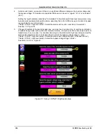
A static switch alarm is generated if there is a significant difference between the inverter voltage and
the bypass voltage. The maximum acceptable difference can be set to “regular” (20 V) or “extended”
(30 V).
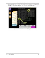
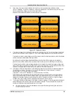
Setting the “synchronization sensitivity” to “extended” in the static switch high level setup screen may
help eliminate repeated static switch alarms, assuming that a 30 V difference upon transfer to bypass
is acceptable for your critical loads.
(“Setup > STSW > High-level setup > Select the static switch synchr. sensitivity > Extended”.)
See item 1 in Figure 81.
5.
If frequent transfers of the load to bypass (say, once per hour) are occurring, it could be an indication
of sudden heavy loads, such as the start current of motors, or inrush current of a non-linear load or of
transformers. In such a case, it is recommended to go to the static switch high level setup and set the
static switch integration time to “extended 20 ms” and set the bypass voltage range to “wide”.
(“Setup > STSW > High-level setup > Select the static switch integration time > Extended 20 ms”.)
(“Setup > STSW > High-level setup > Select the bypass voltage range > Wide”.)
See items 3 and 4 in Figure 81.
Figure 81: Setup > STSW > High-level setup

