G
AMATRONIC
E
LECTRONIC
I
NDUSTRIES
L
TD
.
CENTRIC User Guide, rel. 3.4
89
L
INE
#
A
LARM MESSAGE
OR STATE OF
UPS
E
E
XPLANATION
D
EFAULT
S EVERITY
R
R
ECOMMENDED ACTION
,
IF ANY
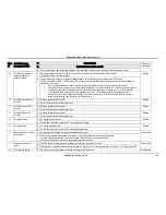
29.
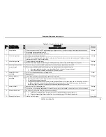
Static switch is sending an
alarm or warning.
E
•
One of the bypass, inverter or output voltages may be out of range.
•
The inverter output voltage may not be synchronized to the bypass voltage
•
The bypass input frequency may be out of range.
Warning
R Perform the instructions in section
10.5
”Troubleshooting “No
output”
”.
30.
Static switch not responding. E There is a problem with communication between the controller and the static switch.
Warning
R
•
Is it just the STSW that isn’t communicating? Is data from the UPS modules being passed to the controller?
•
The controller may not be firmly seated in its shelf, resulting in a bad electrical connection with the communication cable.
•
The controller may be frozen and needs to be rebooted.
•
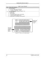
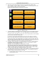
Look at the static switch control panel (Figure 7). Does it appear normal? Is the Alarm LCD lit up?
•
Verify that the communication flat cable is connected firmly on the STSW and on the controller rear.
•
The STSW controller card (PC796) may need replacement.
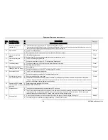
31. Sync fault
(compare with “Short sync
fault”)
E A prolonged (minutes) loss of synchronization occurred between the bypass and the inverter frequencies.
Warning
R
•
This could be due to an unstable bypass source.
•
There may be a problem with the communication cable and its connection to the static switch.
•
If this problem occurs during first-time operation of the UPS, it could be due to improper phase order, or improper definition
of the bypass frequency (60 Hz instead of 50, for example. See “Setup > System > Nominal settings”).
32. Temperature fault.
E The battery temperature sensor has registered a temperature outside of the acceptable range (too high or too low). Measured temperature
can be seen on the “status” screen (tap on the battery icon).
Critical
R
•
The room’s air conditioning may need to be adjusted to lower the air temperature.
•
The temperature sensor may have malfunctioned.
•
The temperature alarm thresholds can be seen at “Setup > Alarms > Set limits > Temperature limits”.
•
See Table 1 on page 7 for recommended air temperature for optimal battery life.
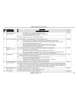
33. The system is operating with
more than one master.
E The system should have only 1 master module, yet the controller says there is more than 1.
Warning
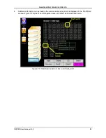
R Go to “Status > Modules > Status”. Click on each module in turn and look at the “Operation mode” field to see which modules are defined
as masters. The first module from the bottom is supposed to be the master. Remove the “other” master (the higher one) and replace it with
a known good module. If you have no replacement module, swap the two master modules. The assumption here is that the upper master
is stuck in master mode, and the lower one is normal and will revert to slave status when moved upward.
34. UPS module N is sending an
alarm or warning.
1
E A problem has been detected by the module’s control logic.
Warning
R Perform the instructions in section
10.4 “Troubleshooting “
UPS modules
”.
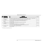
35. UPS shutdown by
E The UPS has turned itself off due to activation of the EPO switch.
Informational

