22
CHAPTER 2 CONNECTION METHOD
2.1
System Configuration
The emulator is designed to be connected to and controlled from a host machine. The
host machine uses emulator debugger software to control the emulator. For
information on using the software, see the Softune Workbench Operation Manual.
■
System Configuration
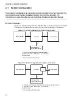
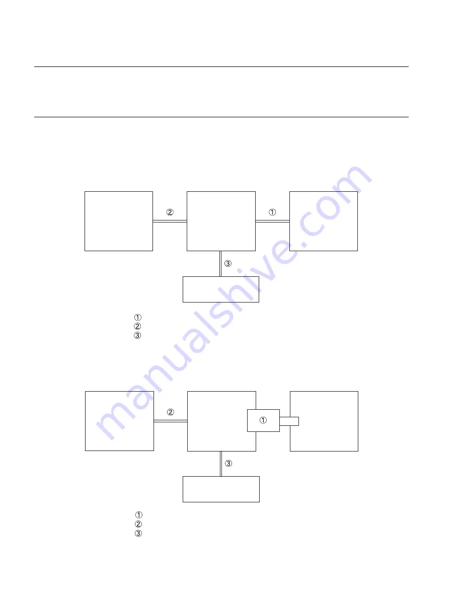
Figure 2.1-1 "System Configuration (if a DSU-FR cable is used)" and Figure 2.1-2 "System
Configuration (if an adapter board is used)" show the system configuration of the emulator.
Figure 2.1-1 System Configuration (if a DSU-FR cable is used)
Figure 2.1-2 System Configuration (if an adapter unit is used)
Host machine
Emulator
User system
Test equipment
(Logic analyzer, etc.)
DSU-FR cable (including an attached cable)*
RS-232C cable *, USB cable *, or LAN cable*
BNC cable*
*: Not included with this product
Host machine
Emulator
User system
Test equipment
(Logic analyzer, etc.)
Adapter unit* (Adapter board plus flat cable plus header board*)
RS-232C cable*, USB cable*, or LAN cable*
BNC cable*
*: Not included with this product
Содержание MB2147-01
Страница 9: ...FUJITSU SEMICONDUCTOR CONTROLLER MANUAL DSU FR EMULATOR MB2198 01 HARDWARE MANUAL CM71 00413 2E ...
Страница 10: ......
Страница 11: ...FUJITSU LIMITED DSU FR EMULATOR MB2198 01 HARDWARE MANUAL ...
Страница 12: ......
Страница 20: ...viii ...
Страница 22: ...x ...
Страница 56: ...34 CHAPTER 2 CONNECTION METHOD ...
Страница 64: ...42 CHAPTER 3 OPERATION METHOD ...
Страница 66: ......
Страница 69: ...47 APPENDIX A DSU FR Cable Specifications Figure A 2 Connector Terminal Arrangement for DSU 3 Pin 1 Pin 30 ...
Страница 76: ...54 APPENDIX B User System Specifications ...
Страница 78: ......
Страница 92: ......

