


53
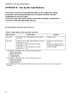
APPENDIX B User System Specifications
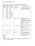
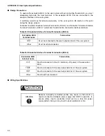
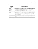
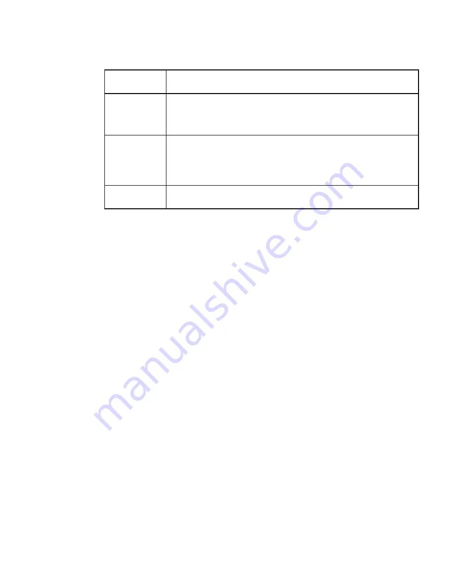
Table B-4 Emulator Interface Wiring Specifications
Signal line
name
Wiring specification
ICLK
ICS[2:0]
ICD[3:0]
BREAK
•
The total wiring length of each signal line (from the evaluation MCU pin
to the Emulator interface connector pin) must be 50 mm or less.
•
The total wiring lengths of every signal line may differ by 2 cm at the
most. The total wiring length of ICLK must be the shortest.
UV
CC
V
CC
T
•
Prepare wiring in a pattern with more capacity than the rated current.
•
An erroneous connection of a probe may cause a short-circuit between
a power source and ground or be a reverse connection. As a safety
measure, include a protective circuit such as a fuse in each of the
power circuit patterns.
GND
•
Connect terminals directly to power circuit patterns, such as the ground
plane.
Содержание MB2147-01
Страница 9: ...FUJITSU SEMICONDUCTOR CONTROLLER MANUAL DSU FR EMULATOR MB2198 01 HARDWARE MANUAL CM71 00413 2E ...
Страница 10: ......
Страница 11: ...FUJITSU LIMITED DSU FR EMULATOR MB2198 01 HARDWARE MANUAL ...
Страница 12: ......
Страница 20: ...viii ...
Страница 22: ...x ...
Страница 56: ...34 CHAPTER 2 CONNECTION METHOD ...
Страница 64: ...42 CHAPTER 3 OPERATION METHOD ...
Страница 66: ......
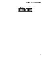
Страница 69: ...47 APPENDIX A DSU FR Cable Specifications Figure A 2 Connector Terminal Arrangement for DSU 3 Pin 1 Pin 30 ...
Страница 76: ...54 APPENDIX B User System Specifications ...
Страница 78: ......
Страница 92: ......